System and methods for improved access to vertebral bodies for kyphoplasty, vertebroplasty, vertebral body biopsy or screw placement

a technology of vertebral body and biopsy, applied in the field of spine surgery, can solve the problems that traditional methods for dealing with compression fractures are not always very effective, and achieve the effect of facilitating the placement of instruments or screws

Active Publication Date: 2009-01-01
LEUCADIA 6 LLC
View PDF4 Cites 14 Cited by
  • Summary
  • Abstract
  • Description
  • Claims
  • Application Information

AI Technical Summary

Problems solved by technology

Traditional methods for dealing with these compression fractures are not always very effective.

Method used


Image

  • System and methods for improved access to vertebral bodies for kyphoplasty, vertebroplasty, vertebral body biopsy or screw placement
  • System and methods for improved access to vertebral bodies for kyphoplasty, vertebroplasty, vertebral body biopsy or screw placement
  • System and methods for improved access to vertebral bodies for kyphoplasty, vertebroplasty, vertebral body biopsy or screw placement

Examples


second embodiment

[0119]In a second embodiment, a second hybrid cannula 600 (FIGS. 34, 35) is advanced into the first pedicle cannula 500. The second cannula 600 is comprised of a matching length radiolucent core inner section or cylinder 602 with radioopaque rings 604 on the ends thereof to correspond to the pedicle cannula 500. The second cannula also has an outer slotted cannula section 606 that extends beyond the skin for percutaneous applications. Furthermore, the second cannula has a suitable interlocking mechanism (not shown) with the first cannula 500 to facilitate appropriate placement with and removal of the first cannula as seen in FIG. 35. The interlocking mechanism may be a snap-fit, screw-fit or similar mechanism.

[0120]The banded guide wire 311 is then removed and the interlocked first cannula 500 and second specialized slotted cannula 600 function as a unit, working portal, for kyphoplasty, vertebroplasty or vertebral body biopsy instruments, as seen in FIG. 35. For pedicle screw place...

third embodiment

[0121]In a third embodiment, the first cannula 500 may be omitted and the second cannula 600 may be inserted over the guide wire 311 directly within the opening created by the drill bit 400. The guide wire 311 is then removed and an appropriate instrument is inserted through the second cannula 600 into the pedicle for a desired procedure, in the manner shown in FIGS. 36-39.

Step 25

[0122]Access for the desired transpedicular procedure then proceeds along the traditional methods. An improvement of current equipment is a modified radioopaque / radiolucent and color banded kyphoplasty balloon catheter, vertebroplasty cannula or vertebral body biopsy needles 700 as seen in FIG. 36 for fluoroscopic imaging.

Step 26

[0123]For kyphoplasty procedures a balloon catheter 702 can be introduced straight and not bent into the first cannula 500 or into the slotted cannula 600, as seen in FIG. 37. The catheter 702 is advanced to the appropriate depth and inflated to proper pressure. Cement or other inje...


PUM


Abstract

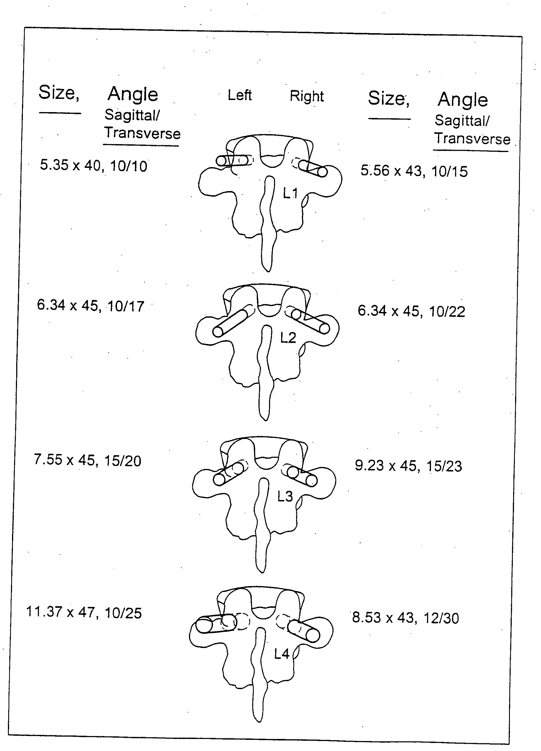
A method of determining the size and / or placement of screws or other instruments in pedicles during surgery in a selected spinal area, comprising generating a dimensionally true three-dimensional image of the bony spine in the selected spinal area; hollowing out the vertebra in the three-dimensional image with cortical wall thicknesses selected by a surgeon performing the surgery; determining the narrowest cross section (isthmus) within each pedicle; generating a straight line starting at the center of the isthmus and extending inwardly to a point centered within the anterior cortex so that it is positioned concentrically within the pedicle without touching the walls thereof, the line terminating inside the vertebral body a predetermined distance from the anterior inner cortical wall and extending outwardly in the opposite direction to penetrate the posterior pedicle cortex; expanding the line concentrically and radially to a cross sectional size that is less than that of the isthmus, the line being expanded into a cylinder that stops growing when any portion thereof contacts the inner cortical wall of the hollowed out vertebral body, with the exception of the posterior pedicle cortex; and calculating the ideal pedicle screw or instrument diameter, length and / or trajectory based on the dimensions and trajectory of the cylinder generated for each pedicle. Also, a new and improved method for providing access to the interior of a pedicle for a desired transpedicular procedure, and a new and improved pedicle cannula construction are disclosed herein.

Description

[0001]This application claims the benefit of U.S. Provisional Patent Application No. 60 / 658,576 filed on Mar. 7, 2005.FIELD OF THE INVENTION[0002]The present invention relates to the general field of spinal surgery and, more particularly, to a manual, computerized or automated method for the accurate sizing and placement of instruments or screws in pedicles during spinal surgical procedures.BACKGROUND OF THE INVENTION[0003]Many medical conditions impact on the human spine anatomy. With the growing elderly population there are an increasing number of patients who are sustaining osteopenic or osteoporotic vertebral body compression fractures that creates significant morbidity and / or mortality for them. Traditional methods for dealing with these compression fractures are not always very effective. As a result, methods to strengthen the vertebral body have evolved with significant clinical improvement for affected patients. A common procedure for this is vertebroplasty in which a bone s...

Claims


Application Information

Patent Timeline
Patent Type & Authority Applications(United States)
IPC IPC(8): A61B19/00
CPCA61B5/055A61B5/6853A61B5/1075A61B5/1076A61B5/4504A61B5/6864A61B6/032A61B17/1757A61B17/8875A61B19/201A61B19/5244A61B2019/462A61B2019/505A61B2019/507A61B5/103A61B34/20A61B90/11A61B2034/105A61B2034/107A61B2090/062A61B2562/17
Inventor PACHECO, HECTOR
Owner LEUCADIA 6 LLC
Why Eureka
Try Eureka