Recording medium tray assembly/disassembly mechanism and image forming apparatus

Inactive Publication Date: 2009-01-08
SAMSUNG ELECTRONICS CO LTD
View PDF0 Cites 0 Cited by
  • Summary
  • Abstract
  • Description
  • Claims
  • Application Information

AI Technical Summary

Benefits of technology

[0013]The present general inventive concept provides a recording medium tray assembly / disassembly mechanism to improve manipulation in an accommodation and ejection of a recording medium tray, and an image forming apparatus to employ the recording medium tray assembly / disassembly mechanism.
[0016]Since the recording medium tray can be disassembled from the image forming apparatus, the accommodation operation or ejection operation of the recording medium tray with respect to the image forming apparatus may be detected by the sensor. The drive mechanism may be connected to the recording medium tray so that the recording medium tray is accommodated at an accommodation complete position and the recording medium tray is ejected from the accommodation complete position, based on the detection by the sensor. Thus, the recording medium tray is automatically accommodated or ejected and simultaneously the recording medium tray is disassembled from the image forming apparatus so that the manipulation can be greatly improved.
[0020]The recording medium tray drive mechanism may include a second elastic member that may be displaced when a manipulation force by the accommodation operation is applied to the drive mechanism. According to the above structure, during the accommodation of the recording medium tray, when the manipulation force of the accommodation operation is applied to the drive mechanism, since the second elastic member is displaced, even when an excess manipulation force by the accommodation operation is applied, the force applied to the drive mechanism can be absorbed by the second elastic member. Thus, the drive mechanism can be prevented from being damaged.
[0027]The recording medium tray assembly / disassembly mechanism may further include at least two members to transfer the drive force of the motor to the second connection portion, wherein the two members function as a friction clutch. According to the above structure, even when an excess manipulation force is applied during the accommodation operation or ejection operation, since a friction clutch is operated, the drive mechanism can be prevented from being damaged.
[0028]The foregoing and / or other aspects and utilities of the general inventive concept may also be achieved by providing an image forming apparatus include the above recording medium tray assembly / disassembly mechanism and a printing portion printing an image on a sheet of recording medium supplied from the recording medium tray. According to the above structure, since the recording medium tray is automatically accommodated and ejected and simultaneously the recording medium tray can be disassembled from the image forming apparatus, the manipulation of the image forming apparatus is greatly improved.

Problems solved by technology

However, although conventional technology assumes that the paper tray is driven by a drive unit, such as a motor or a gear, a drive mechanism is not configured assuming that the paper tray can be disassembled from an image forming apparatus.
However, when the paper tray is pushed into the general image forming apparatus, since the support unit and the paper tray interfere with each other, a change in a force to push the paper tray is generated.
Also, when a number of sheets contained in a recording medium tray in a large image forming apparatus increases, a very large force is needed to manipulate the recording medium tray so that the manipulability is further deteriorated.
However, when the recording medium tray is driven by a drive unit, supporting the recording medium tray at an accommodation complete position and configuring the recording medium tray to be disassembled from the image forming apparatus is not possible.

Method used


Image

  • Recording medium tray assembly/disassembly mechanism and image forming apparatus
  • Recording medium tray assembly/disassembly mechanism and image forming apparatus
  • Recording medium tray assembly/disassembly mechanism and image forming apparatus

Examples


first embodiment

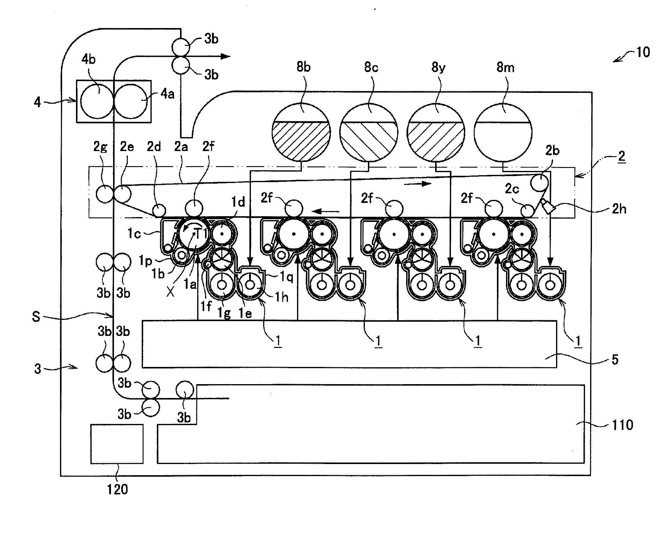
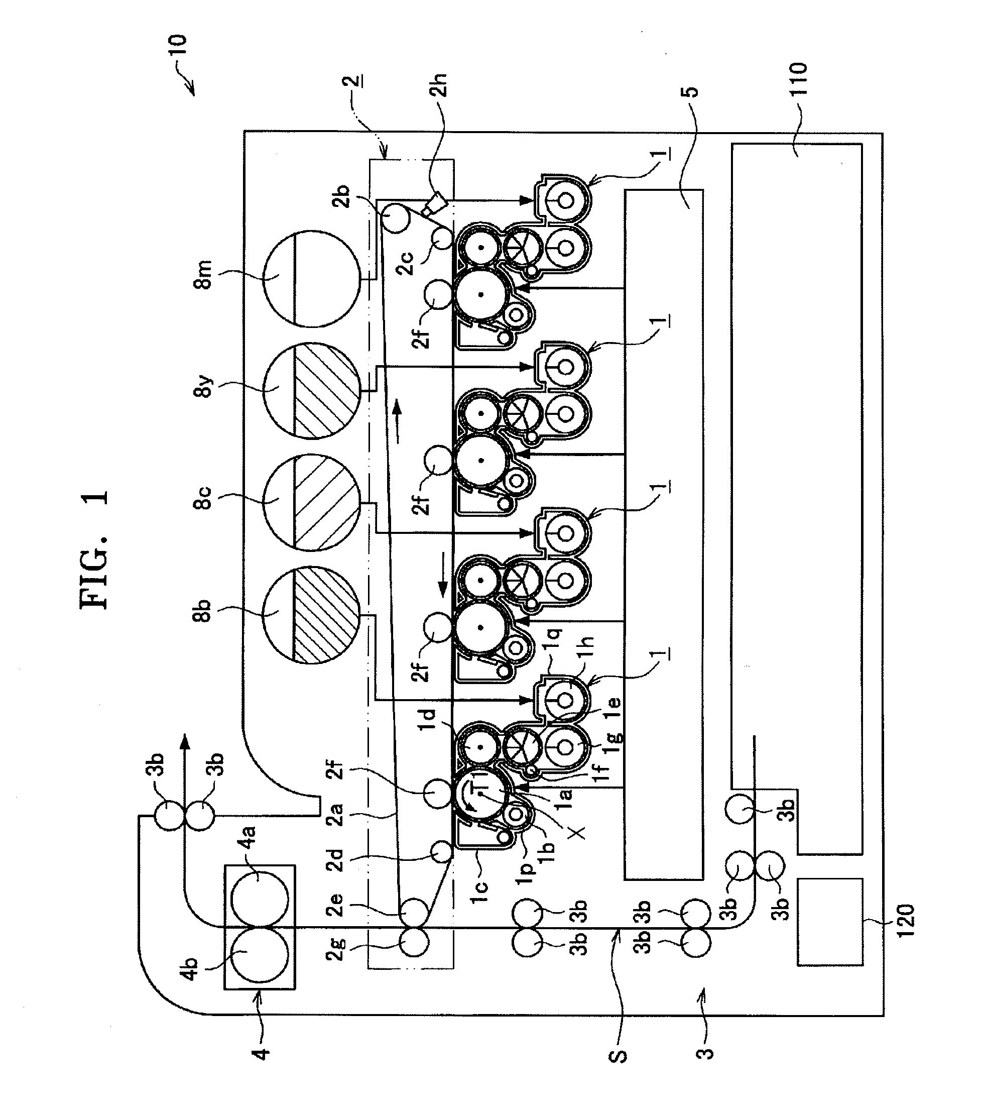
[0056]FIG. 1 illustrates an overall structure of an image forming apparatus 10 according to an embodiment of the present general inventive concept. Referring FIG. 1, the overall structure of the image forming apparatus 10, according to the present embodiment of the present general inventive concept is described below. The image forming apparatus 10 can be of an electrophotographic type such as a copier, a printer, and a facsimile apparatus. The image forming apparatus 10 forms an image using a developer that is a mixture of, for example, a non-magnetic toner and a magnetic carrier.

[0057]The image forming apparatus 10, is of a tandem type, and includes a print portion to print an image on a recording medium S according to an image signal. The print portion includes a plurality of developing units 1 provided for each color of magenta, yellow, cyan, and black according to an image signal of an image to be recorded and forming a toner image of each color, an intermediate transfer body 2...

second embodiment

[0099]FIG. 9 illustrates a drive mechanism 120a of the recording medium tray 110, according to another embodiment of the present general inventive concept. Referring to FIG. 9, the drive mechanism 120a according to the present embodiment includes the motor 122, the deceleration gear 124, a drive gear 200, a rack 202, a member A 204, a member B 206, an extension coil spring A (first elastic member) 208, an extension coil spring B (second elastic member) 210, a pivot hook 212, a torsion spring 214, and a hook guide 216.

[0100]A hook (first connection portion) 116 is disposed at the recording medium tray 110. A position of the hook 116 in a horizontal direction corresponds to the position of the pivot hook 212. An engagement portion 116a to engage the pivot hook (second connection portion) 212 is provided at the hook 116.

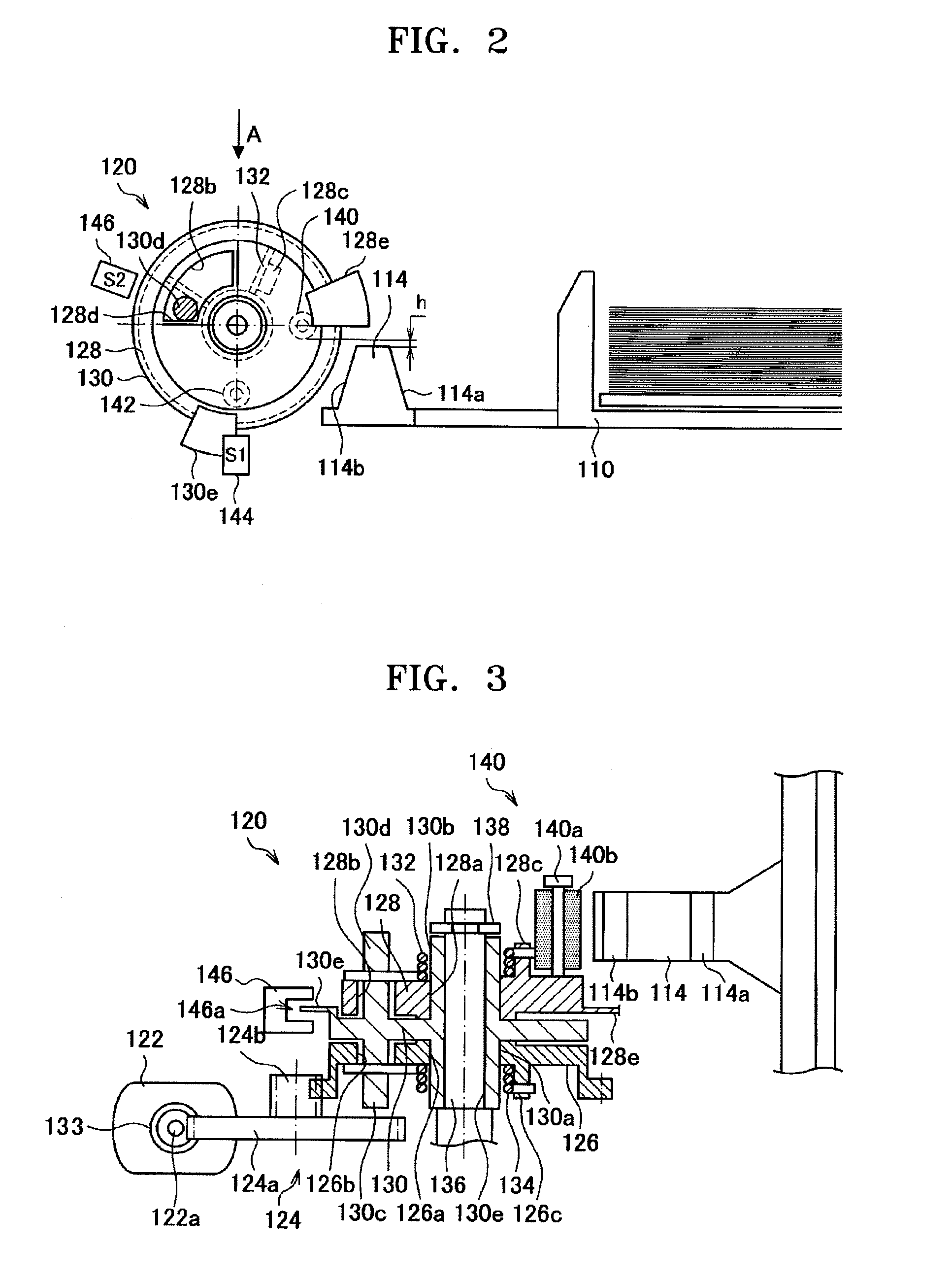
[0101]In FIG. 9, structures of the motor 122 and the deceleration gear 124 are the same as those in the above embodiment described with reference to FIGS. 2-4. The rota...

third embodiment

[0125]FIG. 14 illustrates a structure of a recording medium tray assembly / disassembly mechanism provided in the image forming apparatus 10, according to an embodiment of the present general inventive concept. FIG. 15 illustrates a detailed structure of a drive mechanism 120b, viewed from a direction perpendicular to the direction in which the recording medium tray 110 moves, according to an embodiment of the present general inventive concept. As illustrated in FIG. 14, an engagement portion 112 is provided at the side of the recording medium tray 110. A catch 400 is provided at the main body of the image forming apparatus 10. The structures of the catch 400 and the engagement portion 112 are the same as those of the ones described in FIGS. 22 and 23.

[0126]As illustrated in FIG. 14, the hook 114, protruding in a mountain shape, is disposed at a rear portion of the recording medium tray 110. As illustrated in FIG. 14, the hook 114 has a shape having a width decreasing toward a top por...


PUM


Abstract

A recording medium tray assembly / disassembly mechanism to assemble / disassemble a recording medium tray with respect to an image forming apparatus includes a sensor to detect an accommodation operation or an ejection operation of the recording medium tray with respect to the image forming apparatus, and a drive mechanism to accommodate the recording medium tray at an accommodation complete position or ejecting the recording medium tray from the accommodation complete position by being driven according to the detection by the sensor.

Description

CROSS-REFERENCE TO RELATED APPLICATIONS[0001]This application claims priority under 35 U.S.C. §119(a) from Japanese Patent Application No. 2007-177584, filed on Jul. 5, 2007, in the Japan Patent Office, and Korean Patent Application No. 10-2007-0088298, filed on Aug. 31, 2007, in the Korean Intellectual Property Office, the disclosures of which are incorporated herein in their entirety by reference.BACKGROUND OF THE INVENTION[0002]1. Field of the Invention[0003]The present general inventive concept relates to a recording medium tray assembly / disassembly mechanism and an image forming apparatus including the recording medium tray assembly / disassembly mechanism.[0004]2. Description of the Related Art[0005]An image forming apparatus, such as a copier or printer, includes a paper tray for containing sheets of paper that can be drawn by a main body of the apparatus. When the image forming apparatus is out of paper, the paper tray is ejected and inserted again in the image forming apparat...

Claims


Application Information

Patent Timeline
IPC IPC(8): B65H1/00B41F13/00
CPCB65H1/26B65H2403/532G03G2215/00675G03G15/6508B65H2405/121B65H1/266
Inventor KAWADA, HIDEAKI
Owner SAMSUNG ELECTRONICS CO LTD
Why Eureka
Try Eureka