[0010]To prevent dynamic image blurring by performing the overdrive, an image signal at present (also called a current image signal) and an image signal one sub-frame delayed (a previous image signal) are used. An image signal is corrected in accordance with gradation levels of a current image signal and a previous image signal.
[0012]The present invention has been made in view of the above issue and there is a need for a new and improved image processing apparatus, image processing method, and
computer program capable of improving both dynamic image blurring caused by the hold effect and that caused by slowness of the response speed of liquid
crystal without causing deterioration of
linearity of the gradation.
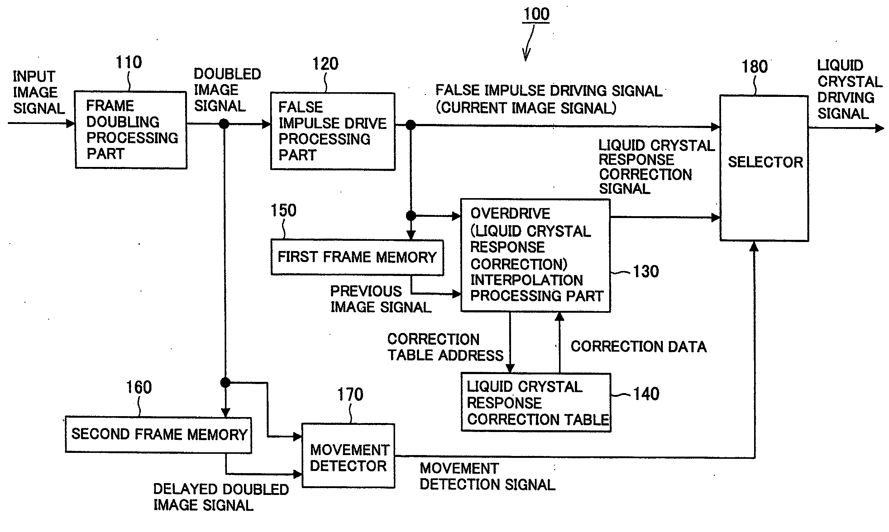
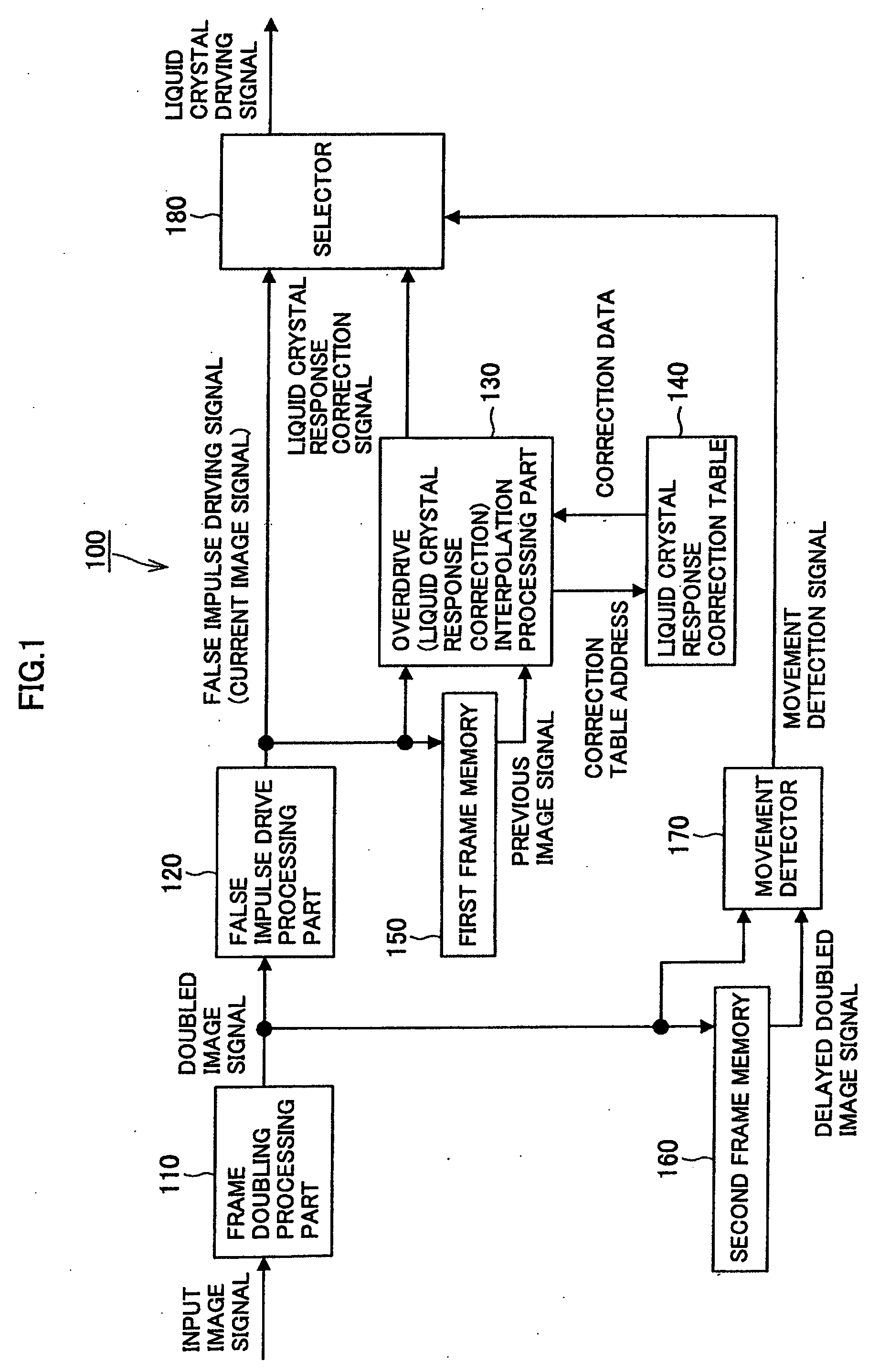
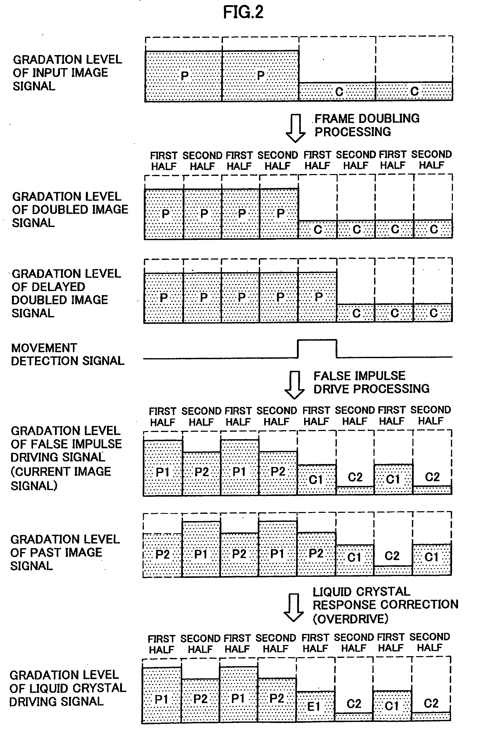
[0014]According to such a configuration, the frame doubling processing part generates a doubled image signal by dividing one frame period of an input image signal that has been input into two sub-frames and repeating the input image signal twice, the false impulse drive processing part divides the doubled image signal generated by the frame doubling processing part into two sub-frames of different gradation levels whose
time integral of luminance realizes luminance in one frame period of the input image signal to output as a current image signal, and the first frame memory outputs a previous image signal delayed by one sub-frame after storing the current image signal output by the false impulse drive processing part. The correction processing part corrects the gradation level of the current image signal in accordance with a difference of the gradation level of the previous image signal and that of the current image signal after the previous image signal output by the first frame memory and the current image signal output by the false impulse drive processing part being input thereto. The second frame memory outputs a delayed doubled image signal delayed by one sub-frame after storing the doubled image signal output by the frame doubling processing part and the movement
detector outputs a
movement detection signal by determining whether a still image or a dynamic image is concerned in accordance with a difference of the gradation level of the delayed doubled image signal and that of the doubled image signal after the delayed doubled image signal output by the second frame memory and the doubled image signal output by the frame doubling processing part being input thereto. Then, the correction processing part corrects the gradation level of the current image signal when the movement detection signal is a signal indicating a dynamic image, and does not correct the gradation level of the current image signal when the movement detection signal is a signal indicating a still image. As a result, when a still image is displayed, both dynamic image blurring caused by the hold effect and that caused by slowness of the response speed of liquid
crystal can be improved without causing deterioration of
linearity of the gradation.
[0016]According to such a configuration, the frame doubling processing part generates a doubled image signal by dividing one frame period of an input image signal that has been input into two sub-frames and repeating the input image signal twice and the false impulse drive processing part divides the doubled image signal from the frame doubling processing part into two sub-frames of different gradation levels whose
time integral of luminance realizes luminance in one frame period of the input image signal to output as a current image signal. The frame memory outputs a delayed doubled image signal delayed by one sub-frame after storing the doubled image signal from the frame doubling processing part and the reversed false impulse drive processing part outputs a signal obtained by dividing the delayed doubled image signal from the frame memory into two sub-frames of different gradation levels whose
time integral of luminance realizes luminance in one frame period of the input image signal and interchanging a first half sub-frame and a second half sub-frame as a previous image signal. The movement
detector outputs a movement detection signal by determining whether a still image or a dynamic image is concerned in accordance with a difference of the gradation level of the delayed doubled image signal and that of the doubled image signal after the delayed doubled image signal from the frame memory and the doubled image signal from the frame doubling processing part being input thereto. Then, the correction processing part corrects the gradation level of the current image signal in accordance with a difference of the gradation level of the previous image signal and that of the current image signal after the previous image signal from the reversed false impulse drive processing part and the current image signal from the false impulse drive processing part being input thereto, and corrects the gradation level of the current image signal when the movement detection signal is a signal indicating a dynamic image and does not correct the gradation level of the current image signal when the movement detection signal is a signal indicating a still image. As a result, when a still image is displayed, both dynamic image blurring caused by the hold effect and that caused by slowness of the response speed of liquid
crystal can be improved without causing deterioration of linearity of the gradation.
[0018]According to such a configuration, the frame doubling processing part generates a doubled image signal by dividing one frame period of an input image signal that has been input into two sub-frames and repeating the input image signal twice and the false impulse drive processing part divides the doubled image signal generated by the frame doubling processing part into two sub-frames of different gradation levels whose time integral of luminance realizes luminance in one frame period of the input image signal to output as a current image signal. The frame memory outputs a previous image signal delayed by two sub-frames after storing a current image signal output by the false impulse drive processing part, and the correction processing part corrects the gradation level of the current image signal in accordance with a difference of the gradation level of the previous image signal and that of the current image signal after the previous image signal from the frame memory and the current image signal from the false impulse drive processing part being input thereto, and has a correction data table having two different pieces of correction data stored therein and switches the correction data table for a first half sub-frame and a second half sub-frame. As a result, when a still image is displayed, both dynamic image blurring caused by the hold effect and that caused by slowness of the response speed of liquid crystal can be improved without causing deterioration of linearity of the gradation.
[0025]According to the embodiments of the present invention described above, when a still image is displayed, a new and improved image processing apparatus, image processing method, and computer program capable of improving both dynamic image blurring caused by the hold effect and that caused by slowness of the response speed of liquid crystal can be provided without causing deterioration of linearity of the gradation.

