Solid state lighting device with heat-dissipating capability

Inactive Publication Date: 2009-01-08
BRIGHT LED ELECTRONICS CORP
View PDF13 Cites 11 Cited by
  • Summary
  • Abstract
  • Description
  • Claims
  • Application Information

AI Technical Summary

Benefits of technology

[0008]Therefore, an object of the present invention is to provide a solid state lighting device that uses thermally conductive mat

Problems solved by technology

While conventional high-power light emitting diodes can produce sufficient amount of light to replace conventional light bulbs, a large amount of heat is generated when large electric currents are supplied thereto.
It is apparent that the substrate 91 impedes

Method used


Image

  • Solid state lighting device with heat-dissipating capability
  • Solid state lighting device with heat-dissipating capability
  • Solid state lighting device with heat-dissipating capability

Examples


Example

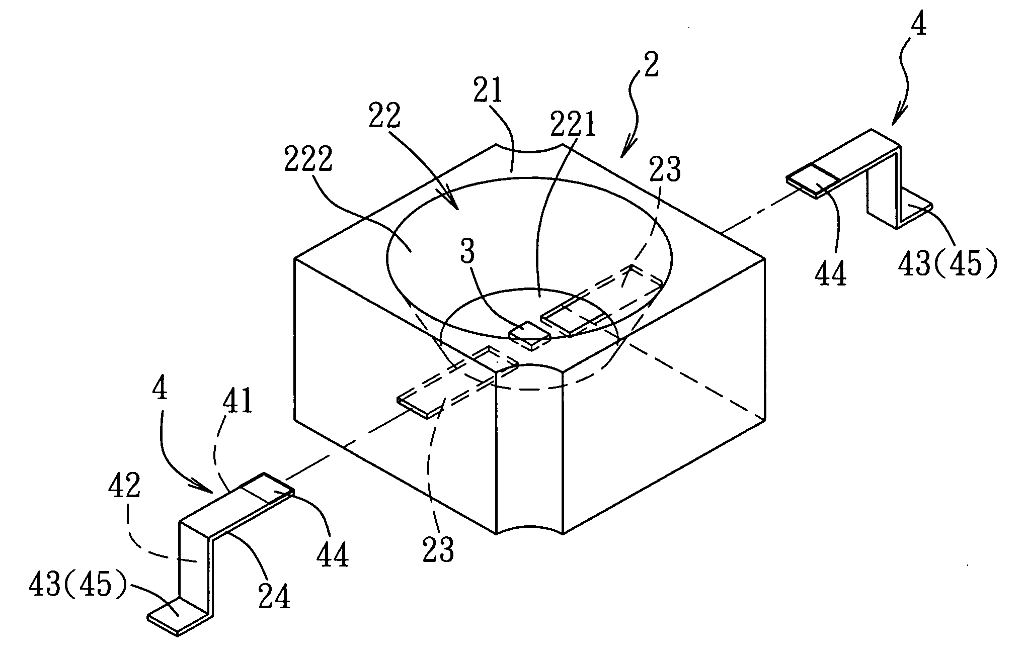
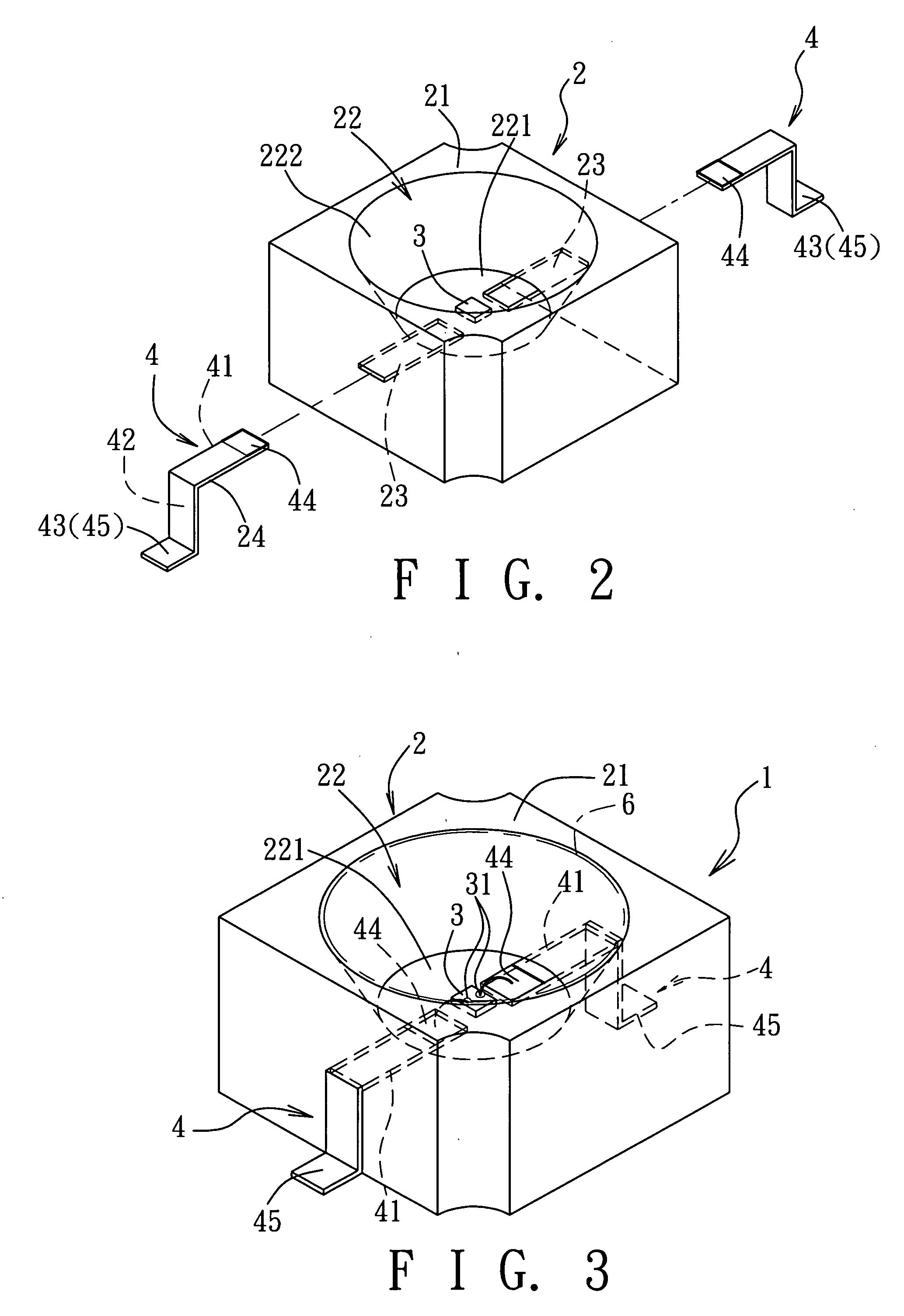
[0027]Referring to FIGS. 2 to 4, the first preferred embodiment of a solid state lighting device 1 with heat dissipating capability according to the present invention is shown to comprise a heat-dissipating base 2, a diode chip 3, a pair of conductive terminals 4, and a light-transmissible layer 6.

[0028]The heat-dissipating base 2 includes a base body 21 formed integrally from a thermally conductive material. The base body 21 has a top side, and is formed with a cavity 22 that is indented from the top side. The cavity 22 is defined by a bottom wall 221 that is spaced apart from the top side of the base body 21, and a surrounding wall 222 that extends from the bottom wall 221 to the top side of the base body 21. The bottom wall 221 and the surrounding wall 222 cooperate to define a frustoconical space to be filled by the light-transmissible layer 6. The base body 21 further has a pair of terminal channels 23, each of which extends from the cavity 22 to an exterior of the base body 21...


PUM


Abstract

A solid state lighting device includes a heat-dissipating base, a diode chip, and a plurality of conductive terminals. The heat-dissipating base includes a base body formed integrally from a thermally conductive material. The base body has a top side, and is formed with a cavity that is indented from the top side. The base body further has a plurality of terminal channels, each of which extends from the cavity to an exterior of the base body. The diode chip is disposed in the cavity. Each of the conductive terminals extends through a respective one of the terminal channels, and has a first connecting part that is disposed in the cavity and that is coupled electrically to the diode chip, and a second connecting part that is disposed outwardly of the heat-dissipating base.

Description

CROSS-REFERENCE TO RELATED APPLICATION[0001]This application claims priority of Taiwanese application no. 096124432, filed on Jul. 5, 2007.BACKGROUND OF THE INVENTION[0002]1. Field of the Invention[0003]The invention relates to a solid state lighting device, more particularly to a solid state lighting device with heat-dissipating capability.[0004]2. Description of the Related Art[0005]While conventional high-power light emitting diodes can produce sufficient amount of light to replace conventional light bulbs, a large amount of heat is generated when large electric currents are supplied thereto. Therefore, the issue of heat dissipation of high-power light emitting diodes is of primary concern to manufacturers.[0006]Referring to FIG. 1, U.S. Patent Application Publication No. US 2005 / 0205889 A1 discloses a high-power light emitting diode (LED) package 9 that includes a substrate 91, a conductive material 94, a LED chip 96, and a lens 99. The substrate 91 is formed with a pair of elec...

Claims


Application Information

Patent Timeline
IPC IPC(8): F21V29/00
CPCH01L33/60H01L33/62H01L33/64H01L33/641H01L2224/48247H01L2224/48465H01L2224/48091H01L2924/00014H01L2924/00H01L2224/73265H01L2924/19107
Inventor TSENG, CHING-LINCHANG, MING-LI
Owner BRIGHT LED ELECTRONICS CORP
Why Eureka
Try Eureka