Drive mechanism and image forming apparatus

Active Publication Date: 2012-05-24
KYOCERA DOCUMENT SOLUTIONS INC
View PDF4 Cites 0 Cited by
  • Summary
  • Abstract
  • Description
  • Claims
  • Application Information

AI Technical Summary

Benefits of technology

[0006]It is an object of the present disclosure to provide a drive mechanism and an image formin

Problems solved by technology

The high temperature environment around the electromagnetic clutch causes malfunctions of the electromagnetic clutch and the dr

Method used


Image

  • Drive mechanism and image forming apparatus
  • Drive mechanism and image forming apparatus
  • Drive mechanism and image forming apparatus

Examples


Embodiment Construction

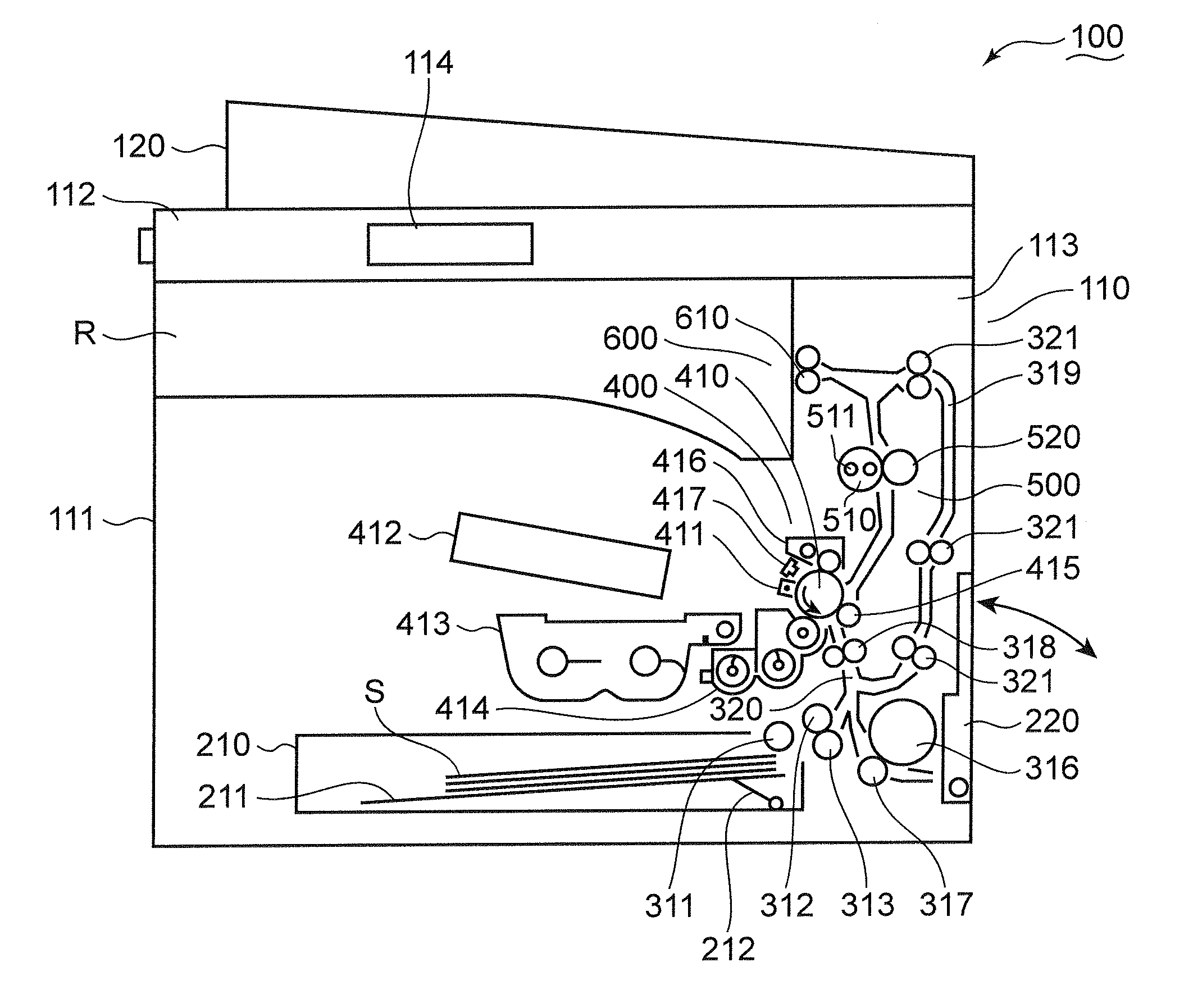
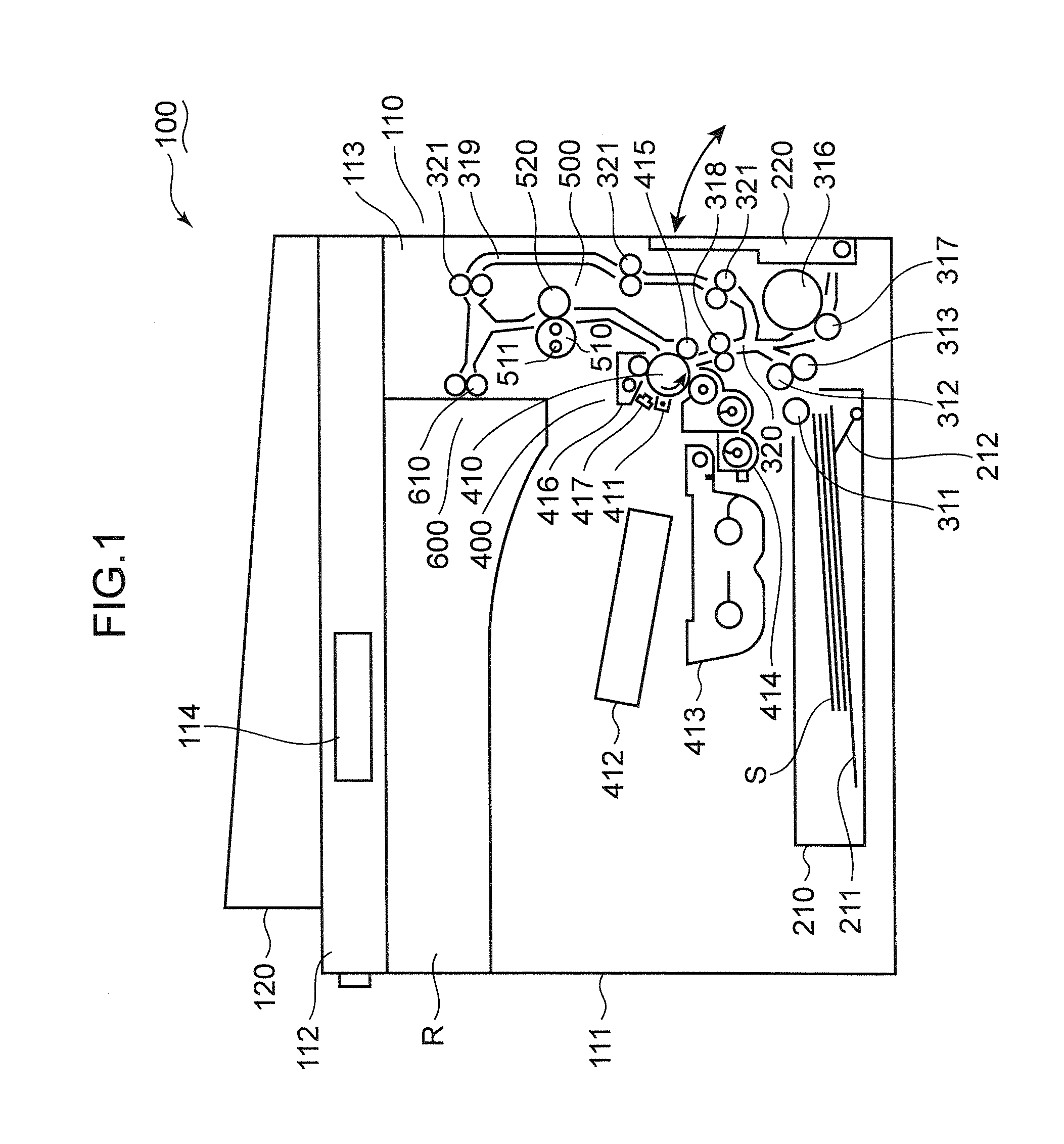
[0017]Various embodiments of an image forming apparatus are described with reference to the accompanying drawings. Directional terms such as “up”, “down”, “left” and “right” used hereinafter are merely intended to clarify the descriptions, and do not in any way limit principles of the drive mechanism or the image forming apparatus. In the following descriptions, the term “sheet” means copy paper, coated paper, OHP sheet, thick paper, card, tracing paper, or another sheet material which is subjected to an image forming process. The terms “upstream”, “downstream” or similar terms used in the following descriptions mean “upstream”, “downstream”, and similar concepts in the sheet conveyance direction.

[0018]FIG. 1 shows a schematic view of an image forming apparatus according to one embodiment. In the present embodiment, a copying machine is exemplified as the image forming apparatus. Alternatively, the image forming apparatus may be a printer or a facsimile device, a composite machine w...


PUM


Abstract

A drive mechanism for transmitting a drive force to drive a processing apparatus which carries out a prescribed process. The drive mechanism includes an output portion, an electromagnetic clutch and a case. An output portion for outputting the drive force, an electromagnetic clutch for controlling transmission of the drive force to the output portion, and a case including a first storage section which defines a first storage room to store the output portion, and a second storage section which defines a second storage room to store the electromagnetic clutch. Additionally, the second storage section includes a peripheral wall which surround the electromagnetic clutch, and a supporting wall which supports the electromagnetic clutch. The peripheral wall includes an upper wall above the electromagnetic clutch and a lower wall below the electromagnetic clutch. An opening section is formed in the upper wall.

Description

BACKGROUND OF THE INVENTION[0001]1. Field of the Invention[0002]The present disclosure is related to a drive mechanism for transmitting a drive force to drive a processing apparatus and an image forming apparatus for forming an image on a sheet by means of the drive mechanism.[0003]2. Description of the Related Art[0004]An image forming apparatus such as copying machines, printers, facsimile machines and composite machines with their functions includes a conveyance portion which conveys sheets, and a drive mechanism which transmits a drive force to drive an image forming mechanism for forming images on the sheets. The drive mechanism typically includes an electromagnetic clutch which controls transmission of the drive force and a cover which prevents chips caused by wearing during operations of the electromagnetic clutch. Since the cover prevents the wear chips from scattering, it becomes less likely that gears around the electromagnetic clutch and other drive elements are worn.[000...

Claims


Application Information

Patent Timeline
IPC IPC(8): B65H5/00F16D27/02
CPCB41J13/00B65H2403/724B65H2402/44B65H3/0669G03G21/00G03G15/00F16D28/00
Inventor KOBAYASHI, TATSUYA
Owner KYOCERA DOCUMENT SOLUTIONS INC
Why Eureka
Try Eureka