Resonating Speaker

Inactive Publication Date: 2009-01-08
WANG YAN MIN
View PDF3 Cites 9 Cited by
  • Summary
  • Abstract
  • Description
  • Claims
  • Application Information

AI Technical Summary

Benefits of technology

[0008]To achieve the above objective, a resonating speaker in accordance with the present invention comprises: an upper cover, an upper magnet, a positioning member, a magnetostrictive member, a coil, a lower magnet, a lower cover and a sound-transmitting member. The upper magnet, the positioning member, the magnetostrictive member, and the lower magnet are disposed in the upper cover. And then the connecting portion of the lower cover is co

Problems solved by technology

The speaker must use a sound box to amplify the sound, which increases the material cost,

Method used


Image

  • Resonating Speaker
  • Resonating Speaker
  • Resonating Speaker

Examples


Embodiment Construction

[0012]The present invention will be clearer from the following description when viewed together with the accompanying drawings, which show, for purpose of illustrations only, the preferred embodiment in accordance with the present invention.

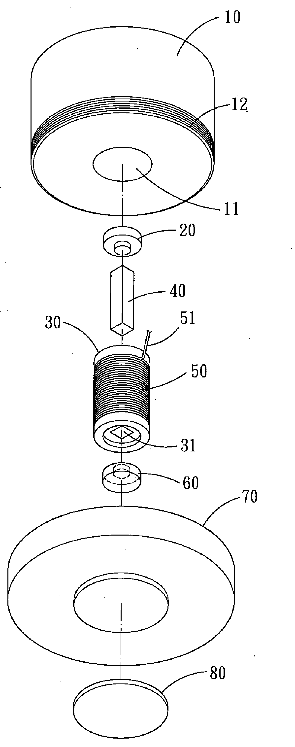
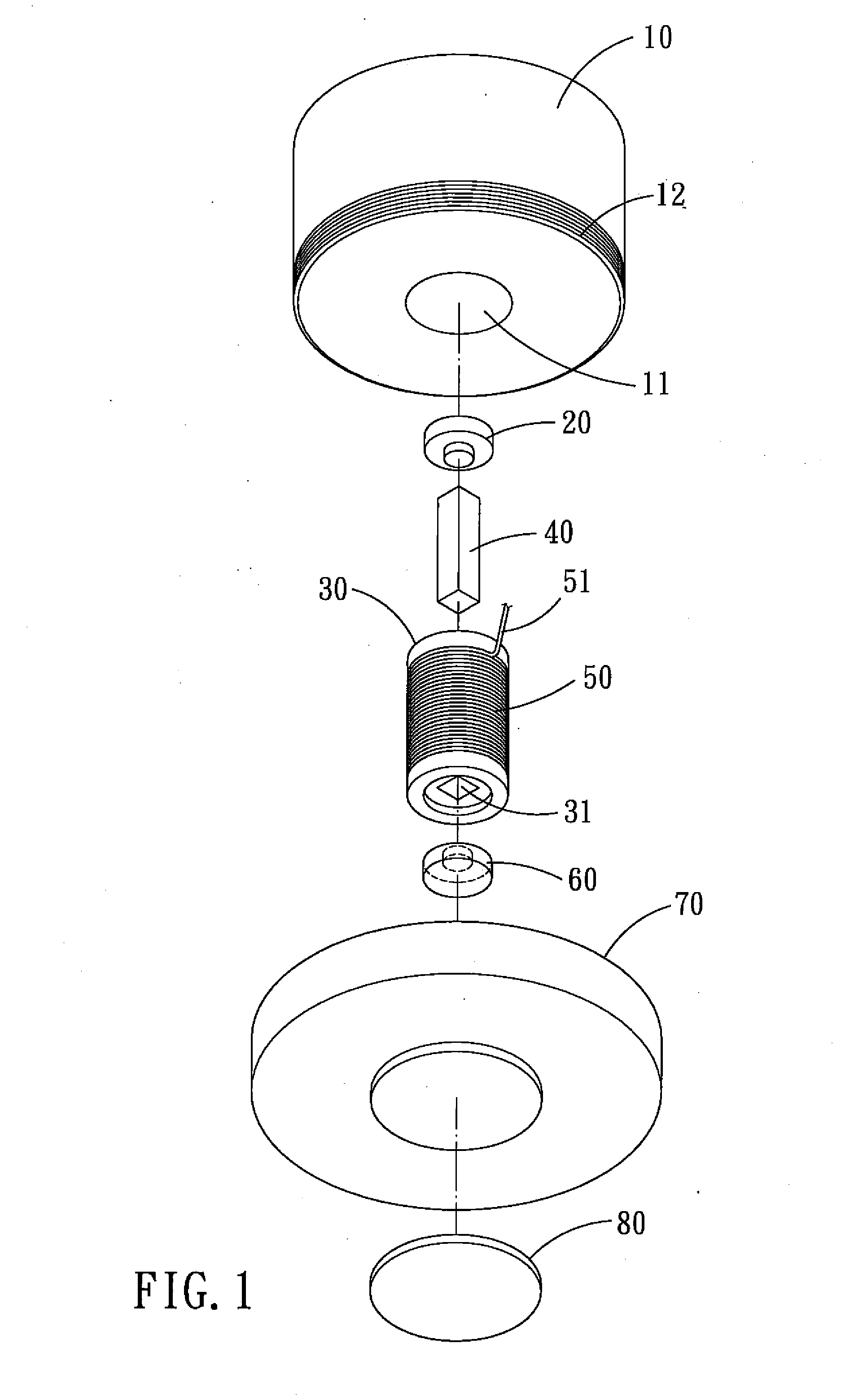
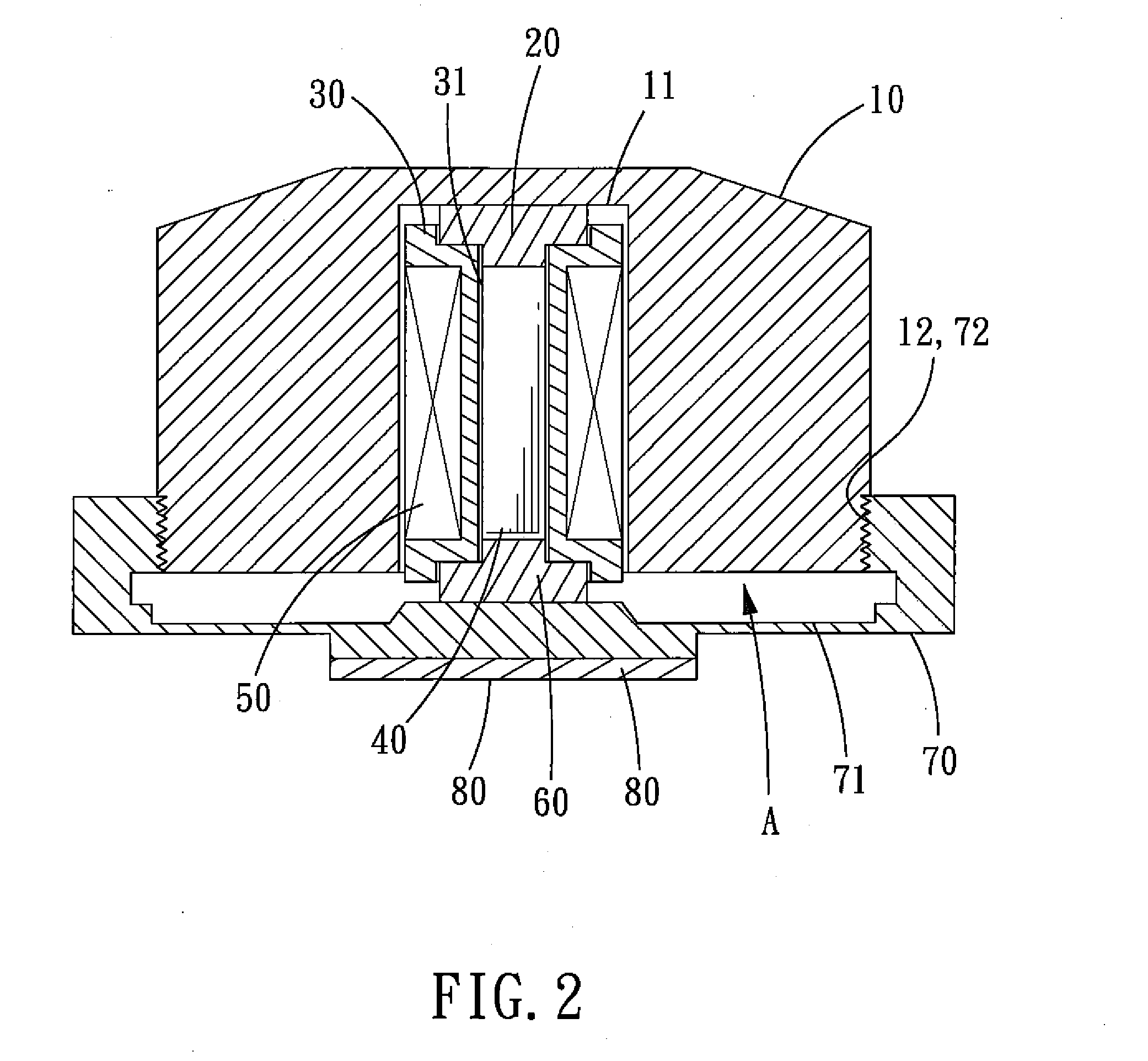
[0013]Referring to FIGS. 1 and 2, a resonating speaker in accordance with a preferred embodiment of the present invention is shown and comprise: an upper cover 10, an upper magnet 20, a positioning member 30, a magnetostrictive member 40, a voice coil 50, a lower magnet 60, a lower cover 70, and a vibration-transmitting member 80.

[0014]The upper cover 10 is an elastic unitary structure made of metal material. In the center of the upper cover 10 is formed an accommodating portion 11 in the form of a circular cavity. An outer threaded connecting portion 12 is formed on the outer peripheral surface of the upper cover 10 and located correspondingly to the accommodating portion 11.

[0015]The upper magnet 20 is received in and pressed against the accomm...


PUM


Abstract

A resonating speaker comprises: an upper cover, an upper magnet, a positioning member, a magnetostrictive member, a coil, a lower magnet, a lower cover and a sound-transmitting member. The upper magnet, the positioning member, the magnetostrictive member, and the lower magnet are disposed in the upper cover. And then the connecting portion of the lower cover is connected to that of the upper cover, so that the lower magnet, the magnetostrictive member, and the upper magnet are pressed onto the upper cover by the upper cover, while leaving resonance space between the upper and lower covers. The vibration-transmitting member is fixed to the lower cover. Hence, the resonating speaker is small and easy to carry, and can play sound simply by puffing it on a sound-transmitting medium.

Description

BACKGROUND OF THE INVENTION[0001]1. Field of the Invention[0002]The present invention relates to a resonating speaker, and more particularly to a resonating speaker which can play sound by putting it on a flat surface as a sound-transmitting medium.[0003]2. Description of the Prior Art[0004]The operation principle of a conventional speaker is to imitate human voice-producing activity-humans produce sound by expelling air through the larynx. However, the speaker is an energy conversion device for converting electric energy into mechanical energy, and then the mechanical energy vibrates the surrounding air to produce sound. That is to say that the speaker is connected to a power source via a power wire, the current flows through the coil of the speaker to produce a magnetic field effect, and then the two permanent magnets at both ends of the coil will repel each other when their positive poles are put together, at this moment, the vibrating membrane of the speaker will shrink inward. ...

Claims


Application Information

Patent Timeline
IPC IPC(8): H04R1/20
CPCH04R15/02H04R9/04
Inventor WANG, YAN-MIN
Owner WANG YAN MIN
Why Eureka
Try Eureka