Image display processing apparatus, image display system, and image display processing method

a technology of image display and processing apparatus, applied in the direction of television system, color signal processing circuit, instruments, etc., can solve the problems of difficult to match the color of the entire, difficult to display a realistic image, and inability to control the color of the light beam, etc., to achieve the effect of not reducing the sense of realism

Inactive Publication Date: 2009-01-08
OLYMPUS CORP
View PDF0 Cites 24 Cited by
  • Summary
  • Abstract
  • Description
  • Claims
  • Application Information

AI Technical Summary

Benefits of technology

[0008]This invention has been made to solve the above-mentioned problem, and an object of this invention is therefore to provide a technique capable of displaying an image without reducing the sense of realism even in the observation environment in which the environment illuminant includes the external light or the light emitted from a light source other than the illumination device for reproducing.

Problems solved by technology

Colors of these light beams cannot be controlled.
Therefore, with only the control of the color of the light emitted from the illumination device for reproducing according to the input illuminant as disclosed in JP 2005-341122 A, it may be difficult to match the color of the entire environment illuminant illuminating the observation environment with the color of the input illuminant in the observation environment in which the environment illuminant includes the external light or the light emitted from another light source.
When such matching is difficult, it may be difficult to display a realistic image.

Method used


Image

  • Image display processing apparatus, image display system, and image display processing method
  • Image display processing apparatus, image display system, and image display processing method
  • Image display processing apparatus, image display system, and image display processing method

Examples


first embodiment

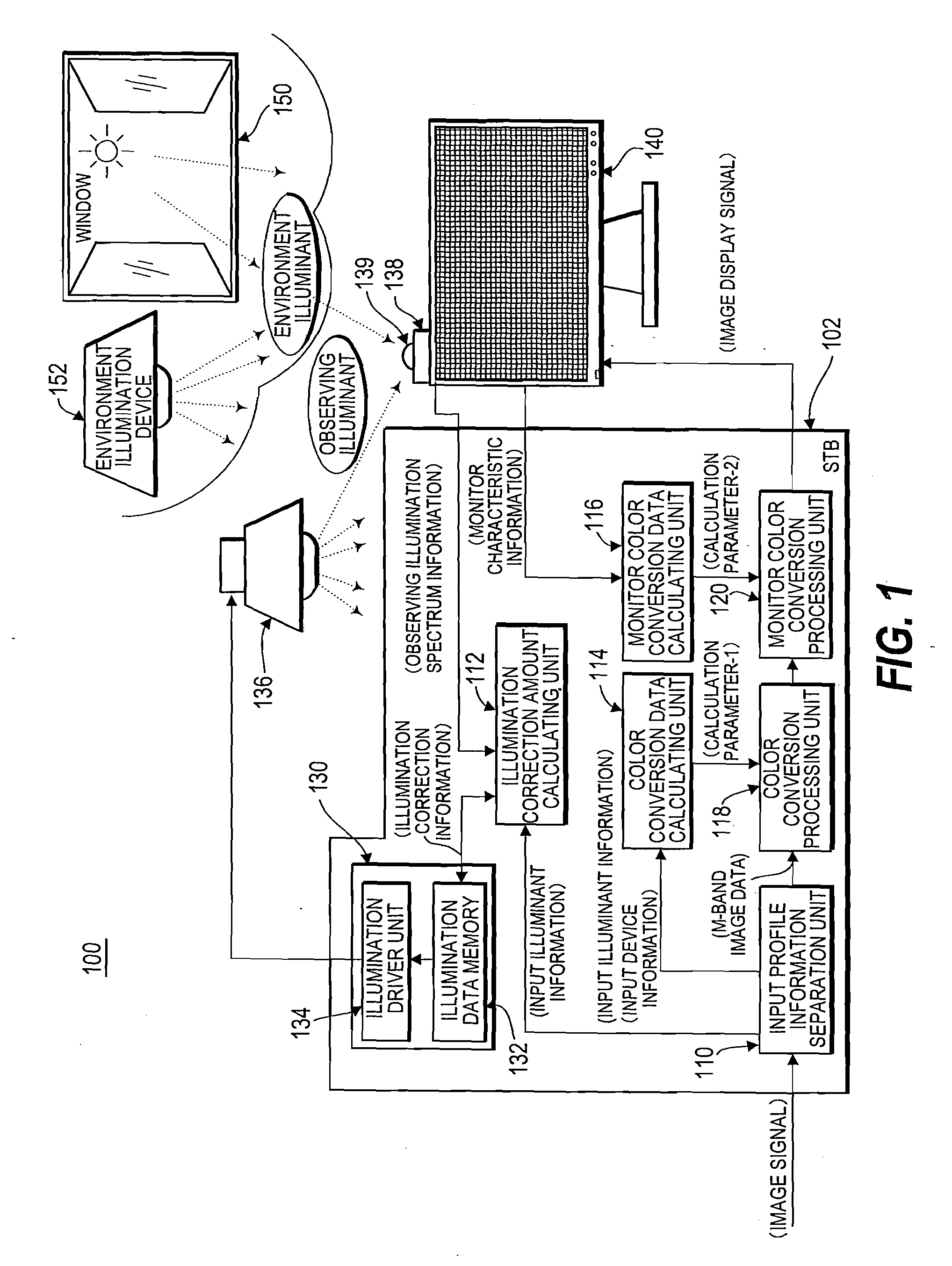
[0064]FIG. 1 is a schematic block diagram showing a structure of an image display system according to a first embodiment of this invention. An image display system 100 includes a set top box (hereinafter, referred to as “STB” in this specification) 102, a variable characteristic illumination device 136, a spectrometer unit 138, and a monitor display device (hereinafter, referred to as “display device” in this specification) 140. The image display system 100 is provided in, for example, a room in a house. The room includes an illumination device such as a ceiling light and a window. Light is emitted from the illumination device. For example, sunlight enters into the room through the window. In this embodiment, for example, the room in which the image display system 100 is provided corresponds to an “observation environment” described above. The illumination device which is previously provided in the room or is not included in the image display system 100 corresponds to an “environmen...

second embodiment

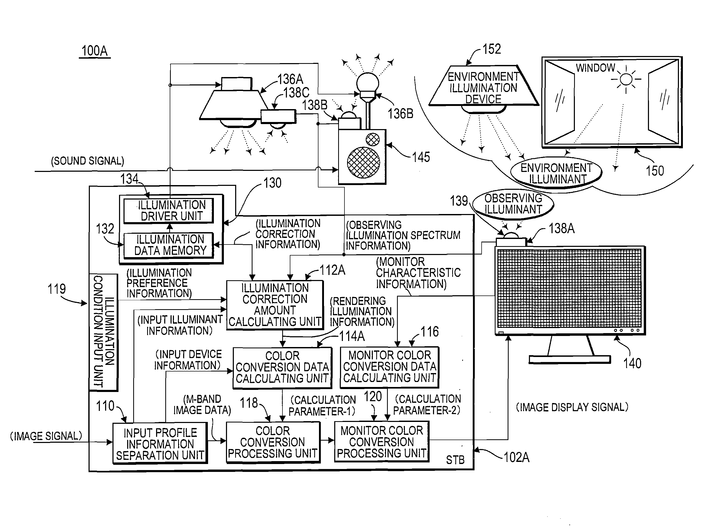
[0092]FIG. 5 is a schematic block diagram showing a structure of an image display system according to a second embodiment of this invention. In an image display system 100A shown in FIG. 5, the same constituent elements as those of the image display system 100 shown in FIG. 1 are denoted by the same reference symbols and the description thereof is omitted here. Points different from the image display system 100 shown in FIG. 1 will be mainly described.

[0093]The image display system 100 according to the first embodiment includes the single variable characteristic illumination device 136 and the single spectrometer unit 138. In contrast to this, the image display system 100A according to the second embodiment includes an STB 102A, a plurality of variable characteristic illumination devices 136A and 136B and a plurality of spectrometer units 138A, 138B, and 138C. FIG. 5 shows the example in which the two variable characteristic illumination devices and the three spectrometer units are ...


PUM


Abstract

An image display processing apparatus receives input illuminant information relating to input illuminant illuminating object when photographing, input device information specifying input characteristic of a photographing device, and image signal. Spectral reflectance image signal of the object is obtained from the image signal, the input illuminant information, and the input device information. Rendering light is applied to the spectral reflectance image signal, and output to a display device. A spectrum of light emitted from a variable characteristic illumination device for illuminating a display viewing environment can be varied. Spectrum of observing illuminant illuminating the display viewing environment is measured by a spectrometer unit. A spectrum of the rendering light is determined to substantially match with a spectrum of the input illuminant. The spectrum of the light emitted from the variable characteristic illumination device may be adjusted to substantially match the spectra of both the rendering light and the observing illuminant.

Description

FIELD OF THE INVENTION[0001]This invention relates to an image display processing apparatus for displaying an image using a color monitor display device, an image display system, and an image display processing method.DESCRIPTION OF THE RELATED ART[0002]There has been known the following method of representing a multicolor image with at least three primary colors to enable more faithful and natural color reproduction. In the method, an object is photographed using a camera capable of performing multi-band photographing, for example, 16-band color photographing, which is called a multi-spectral camera. The obtained image data, characteristics of the camera for photographing, and spectral characteristics of illuminating light for illuminating the object at the time of photographing are used to produce an image signal represented by a spectral reflectance of the object. The image signal represented by the spectral reflectance of the object is called a spectral reflectance image signal....

Claims


Application Information

Patent Timeline
IPC IPC(8): G06K9/00H04N5/228H04N7/173H04N9/64H04N21/2187H04N21/235H05B37/02
CPCG09G2360/144G09G5/02
Inventor HORIE, TAKUJIFUKUDA, HIROYUKIMATSUSHITA, AKIRAAJITO, TAKEYUKIKOMIYA, YASUHIROIOKA, KEN
Owner OLYMPUS CORP
Why Eureka
Try Eureka