System and method for forward path gain control in a digital predistortion linearized transmitter

a linearized transmitter and forward path technology, applied in the field of digital communication, can solve the problems of reducing linearization performance, leaking energy into neighboring frequency bands, and large distortion components of output signals

Inactive Publication Date: 2006-05-11
INTEL CORP
View PDF9 Cites 19 Cited by
  • Summary
  • Abstract
  • Description
  • Claims
  • Application Information

AI Technical Summary

Benefits of technology

[0010] In a preferred embodiment of the method, the local gradient is estimated by iteratively comparing actual gain adjustments to gain adjustment settings. The gain adjuster settings are preferably restricted to a relatively linear portion of the analog gain adjuster characteristic. For example, the gain adjuster settings are preferably restricted to a region of the characteristic where the gradient is within a predetermined limit. Also, the step size of the change in gain adjuster setting is preferably restricted to be within a predetermined limit. The analog gain adjuster may be a voltage variable attenuator. The gain adjuster settings are then digital control voltage values and the method further comprises converting the digital control voltage values to analog control voltages.
[0011] According to another aspect the present invention provides a predistortion linearized transmitter. The transmitter comprises an input for receiving a digital input signal and a predistorter receiving the digital input signal and operating on the input signal with a predistortion operation including a digital gain adjustment. The transmitter further comprises a conversion and frequency translation circuit block for converting the predistorted input signal to a higher frequency analog signal and an analog gain adjuster receiving and gain adjusting the analog signal. An amplifier receives and amplifies the gain adjusted analog signal and provides an amplified output signal. An output sampling coupler is coupled to the amplifier output and provides an analog sampled ...

Problems solved by technology

Modern high capacity modulation techniques exhibit large amplitude variation, which result in large distortion components on the output signal, leaking energy into neighboring frequency bands.
These techniques are very sensitive to the system gain, the variation of which can effectively un-calibrate the predistortion signal (the compensation applied to the signal reaching the non-linear component i...

Method used


Image

  • System and method for forward path gain control in a digital predistortion linearized transmitter
  • System and method for forward path gain control in a digital predistortion linearized transmitter
  • System and method for forward path gain control in a digital predistortion linearized transmitter

Examples


Embodiment Construction

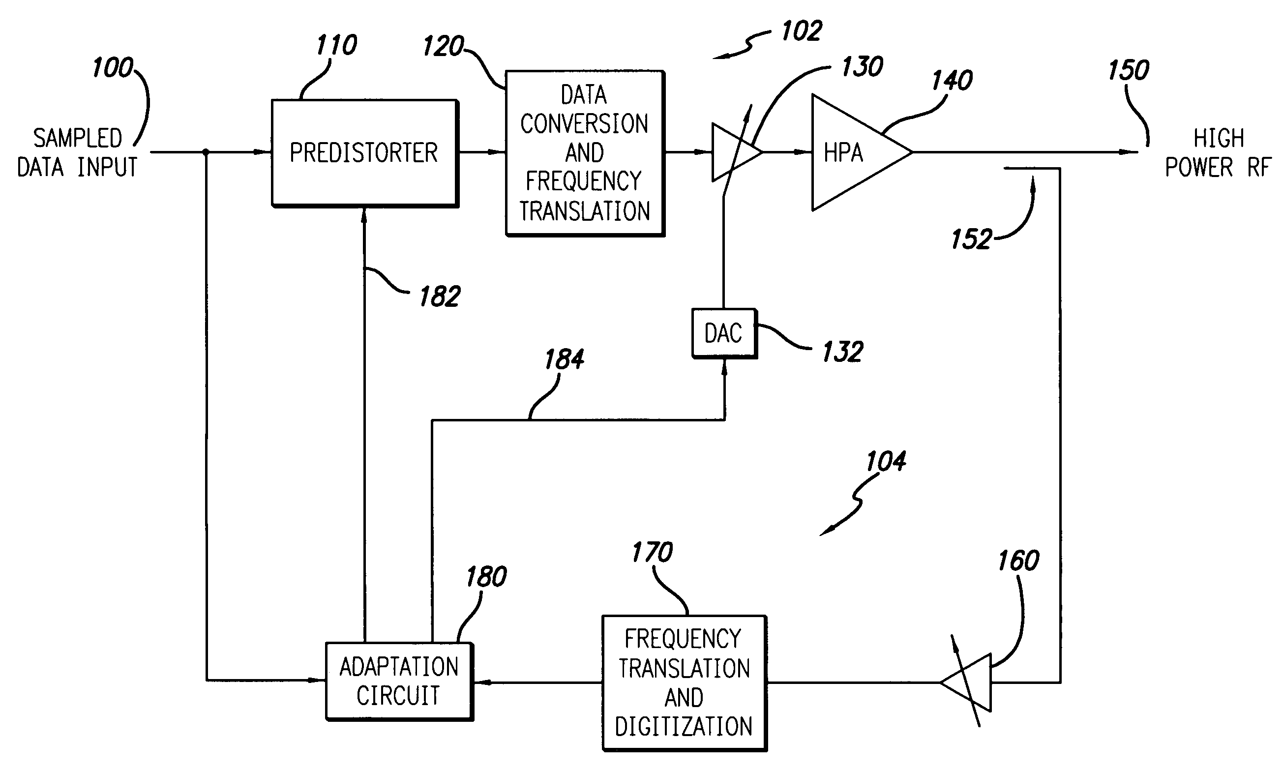
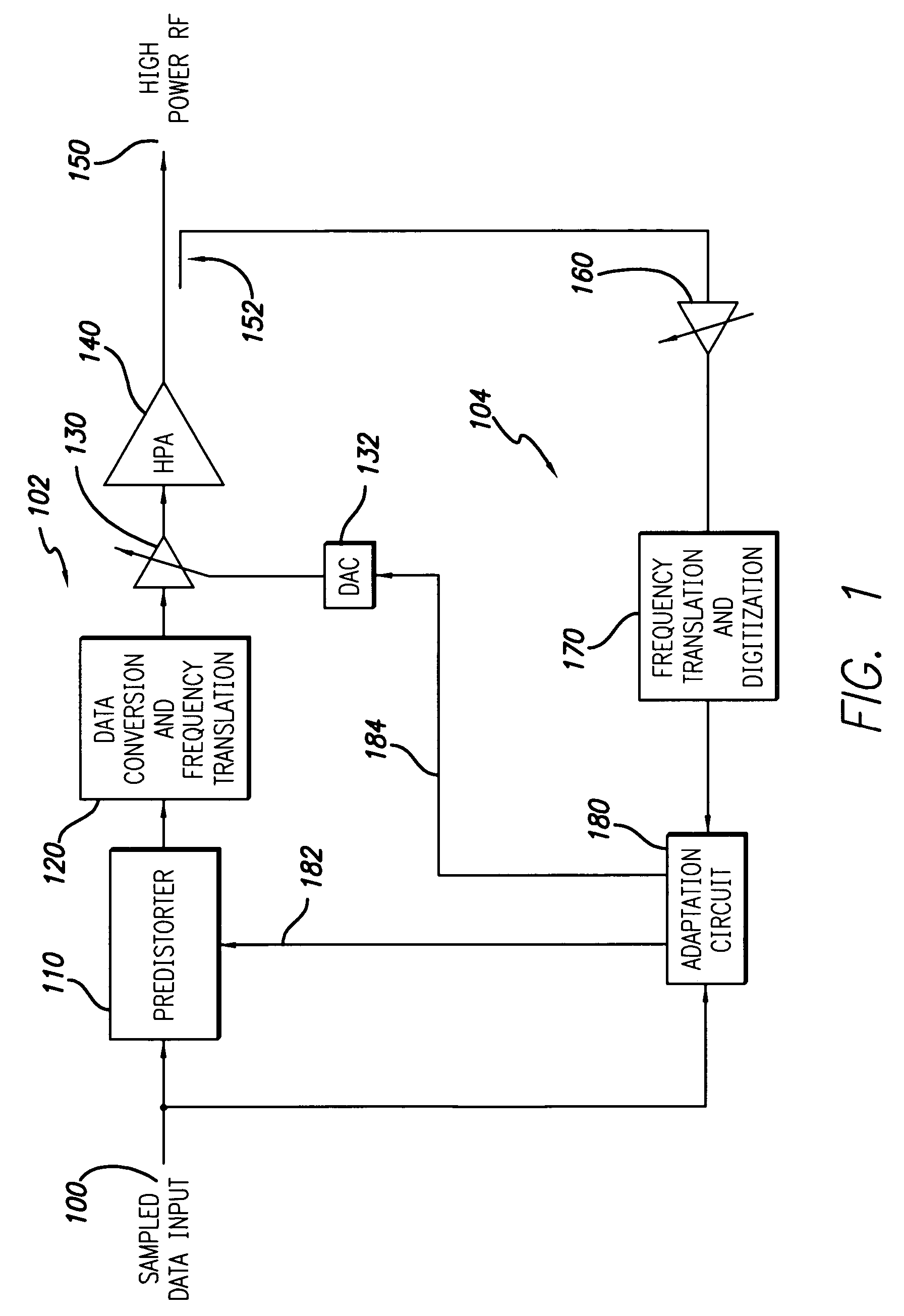
[0018]FIG. 1 shows a digital predistortion linearized transmitter in accordance with a preferred embodiment of the present invention. The transmitter includes a forward signal path 102 and an observation signal path 104. The forward signal path includes a sampled data input 100 which receives a conventional digital communication signal such as a wideband CDMA or other well known digitally modulated signal. As well known to those skilled in the art, in general the input signal may be a complex digital signal provided in quadrature (I,Q) format and single lines are shown in the figures simply for ease of illustration. The input signal is modified by the predistorter 110 to compensate for the non-linear characteristic of the high power amplifier (HPA) 140. The predistorted signal is then converted to an RF signal by a conventional data conversion and frequency translation function block 120. The forward path analog gain is controlled by an RF variable voltage attenuator (VVA) 130, whic...


PUM


Abstract

A system and method for controlling the gain in the forward signal path of a digital predistortion linearizer is disclosed. The loop gain of the predistortion system is driven to unity, where a separately controlled constant-gain observation path allows accurate gain control of the forward path. This is divided into digital gain from the predistortion function and analog gain from a Voltage Variable Attenuator (VVA) in the transmitter. The invention balances the distribution between these two domains in order to maximize dynamic range and minimize noise in the forward signal path. In order to distribute the forward path gain accurately, the characteristic of the VVA must be well known. Since these devices tend to be non-linear, with variable characteristic over temperature and batch, the invention compensates for this non-linear behavior by tracking the varying transfer characteristic of the VVA, giving a predictable local characteristic. Another aspect of the disclosed invention is the ability to operate with very low transmit power and loop gain levels, allowing accurate gain control during such scenarios as cell initialization, that require operation over a wide dynamic range.

Description

RELATED APPLICATION INFORMATION [0001] The present application claims priority under 35 USC Section 119(e) to provisional application Ser. No. 60 / 626,755 filed Nov. 10, 2004, the disclosure of which is incorporated herein by reference in its entirety.FIELD OF THE INVENTION [0002] The present invention relates to the field of digital communication. More specifically the present invention relates to the field of radio transmitters incorporating digital predistortion linearization. BACKGROUND OF THE INVENTION [0003] Efficiency is an important metric of high power amplifiers. In order to achieve maximum efficiency these amplifiers are often biased into strongly non-linear modes of operation. Modern high capacity modulation techniques exhibit large amplitude variation, which result in large distortion components on the output signal, leaking energy into neighboring frequency bands. [0004] Predistortion techniques attempt to compensate for the power amplifier non-linearity by applying an ...

Claims


Application Information

Patent Timeline
IPC IPC(8): H04L25/49
CPCH04L27/3809
Inventor LUKE, CHRISTIAN G.JOHNSON, IANCOPE, MARKMANSELL, ADRIANWOOD, STEVEN ANDREW
Owner INTEL CORP
Why Eureka
Try Eureka