Electrical systems architecture for an aircraft, and related operating methods

a technology of electric systems and aircraft, applied in the direction of positive displacement liquid engines, energy-efficient board measures, electric generator control, etc., can solve the problems of increased ecs power consumption and reduced airplane fuel consumption compared with current production aircraft, adverse effects on engine fuel economy,

Active Publication Date: 2009-05-21
THE BOEING CO
View PDF42 Cites 19 Cited by
  • Summary
  • Abstract
  • Description
  • Claims
  • Application Information

AI Technical Summary

Problems solved by technology

When pneumatic bleed air is extracted from an engine, this work (performed by the engine) does not help to produce thrust, so engine fuel economy is adversely affected.
A traditional pneumatic architecture would not be cost effective in a smaller, lightweight aircraft that must satisfy new FAA requirements for passenger fresh air flow (which will result in greater ECS power consumption and reduction in airplane fuel consumption compared with current production aircraft).
However, they are large, heavy, and require a special liquid cooling system to address the high densities of heat that are generated during power conversion.
The all-electric architecture can generally be characterized as being efficient for long flights, but very complex.
Consequently, such an all-electric architecture may not be the best approach for a smaller aircraft with a lower target cost and shorter mission range.
A traditional all-electric architecture ceases to be cost effective or meet cost and weight targets when it is scaled down to meet the needs of a much smaller aircraft.
In particular, the large motor controllers and power conversion equipment required to operate major systems on the aircraft from power sources that produce variable frequency AC power are bulky, heavy, costly, and require a special liquid cooling system.
In addition, many smaller motor loads located throughout the aircraft require motor controllers to be compatible with variable frequency AC power, resulting in added complexity, cost and weight.
Although the efficiency gained for long flights is better for the all-electric architecture than for a traditional pneumatic system, the all-electric architecture has not been demonstrated to be the most cost effective approach for a much smaller aircraft with shorter range.

Method used


Image

  • Electrical systems architecture for an aircraft, and related operating methods
  • Electrical systems architecture for an aircraft, and related operating methods
  • Electrical systems architecture for an aircraft, and related operating methods

Examples


Embodiment Construction

[0021]The following detailed description is merely illustrative in nature and is not intended to limit the embodiments of the subject matter or the application and uses of such embodiments. Furthermore, there is no intention to be bound by any expressed or implied theory presented in the preceding technical field, background, brief summary or the following detailed description.

[0022]Techniques and technologies may be described herein in terms of functional and / or logical block components, and with reference to symbolic representations of operations, processing tasks, and functions that may be performed by various computing components or devices. It should be appreciated that the various block components shown in the figures may be realized by any number of hardware, software, and / or firmware components configured to perform the specified functions. For example, an embodiment of a system or a component may employ various integrated circuit components, e.g., memory elements, digital s...


PUM


Abstract

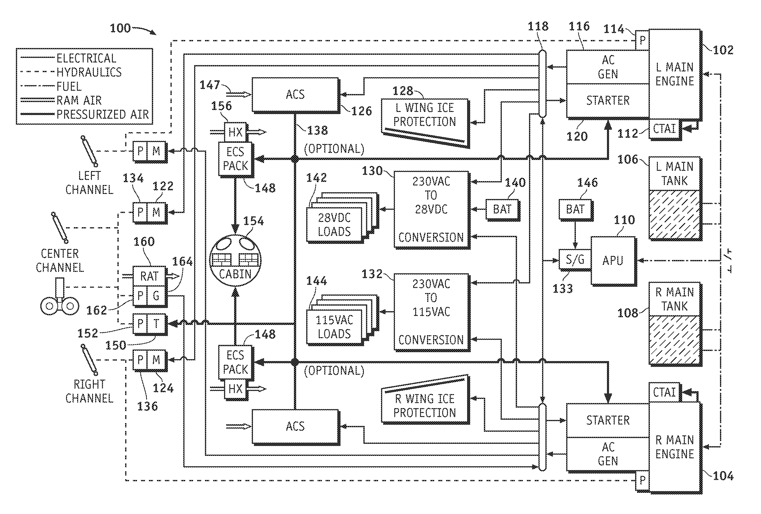
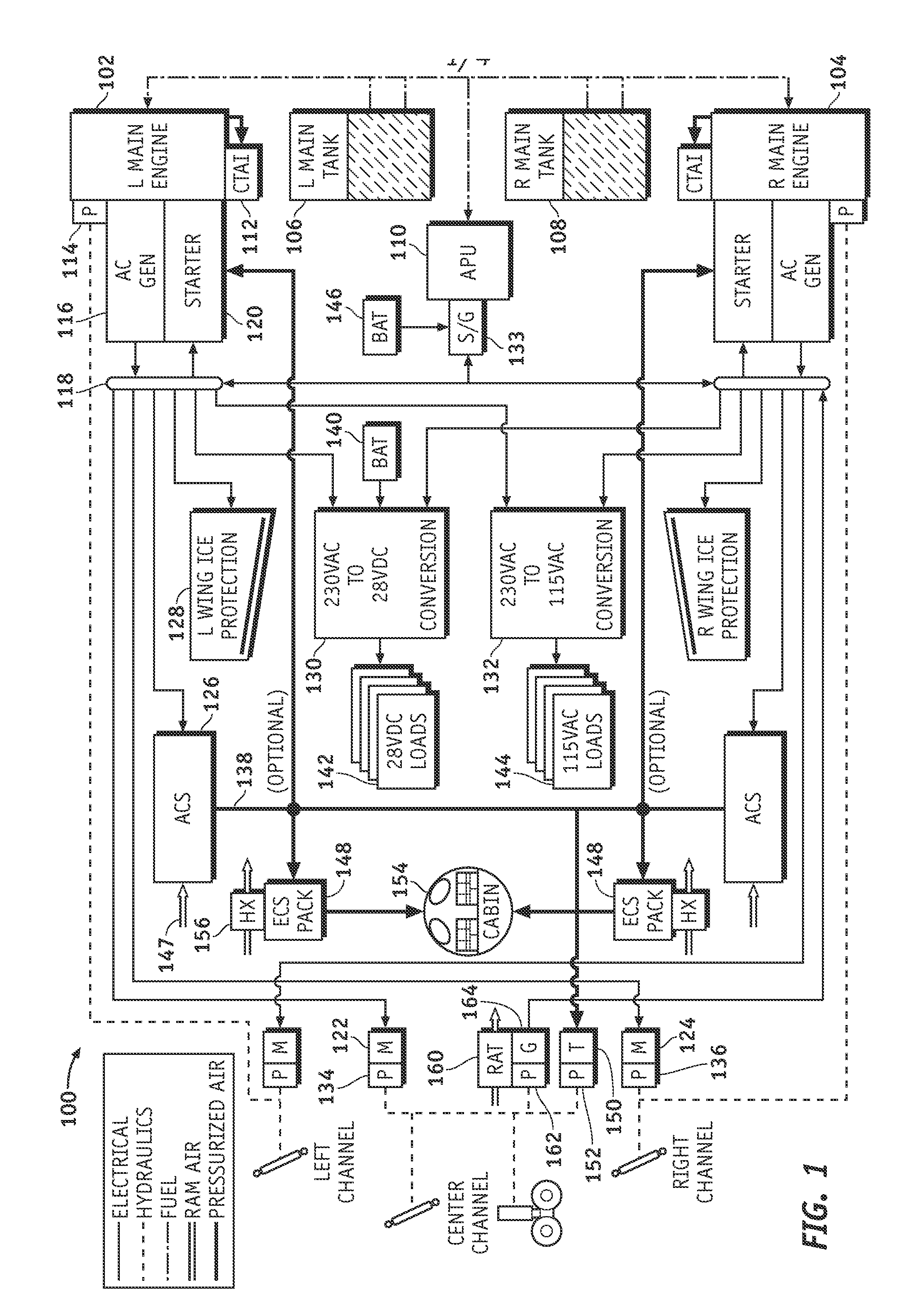
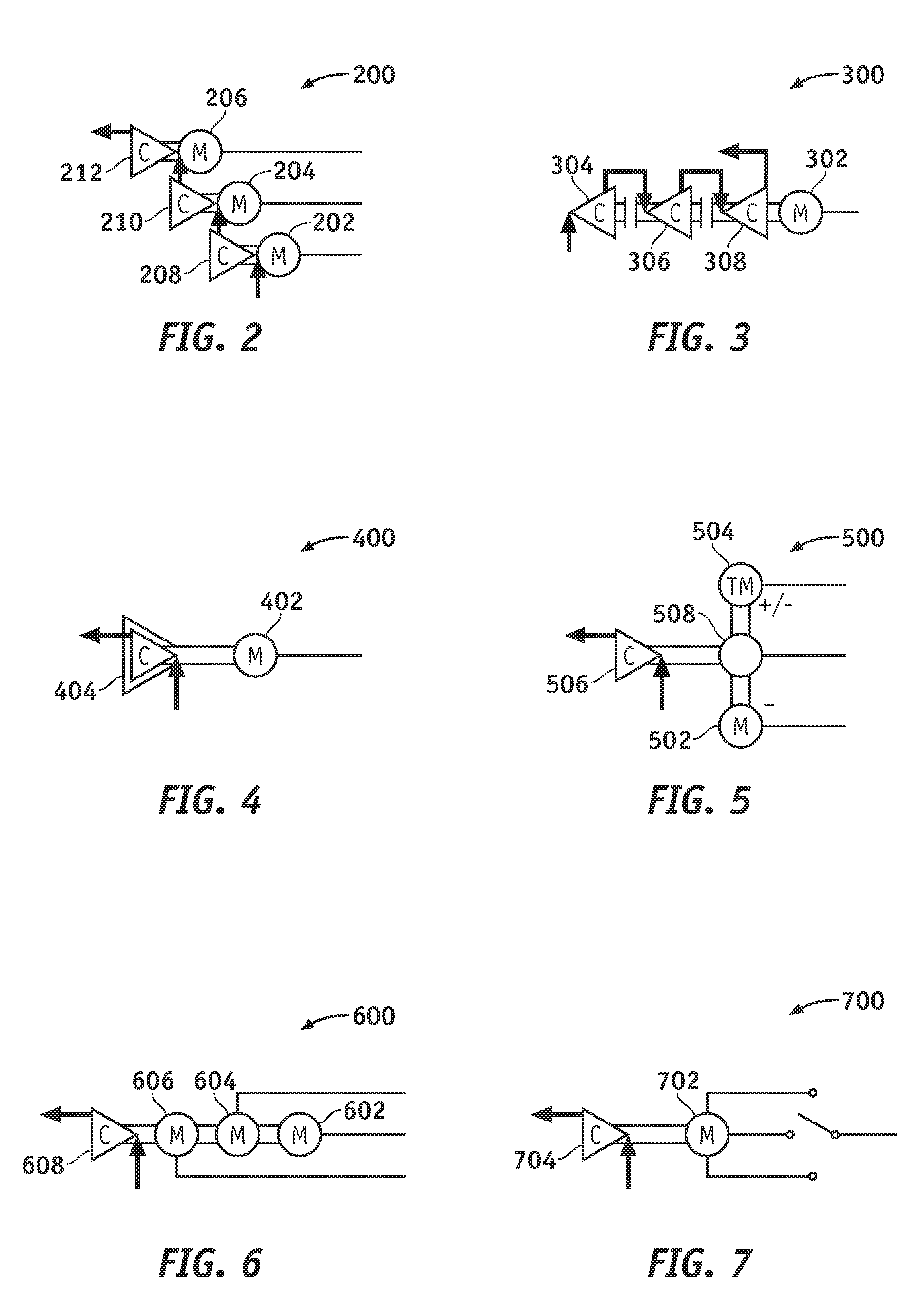
An electrical architecture for an aircraft is provided. The electrical architecture is particularly suitable for relatively small, compact, and lightweight aircraft. In one embodiment, the electrical architecture includes an electrical generator component coupled to the aircraft engine, and an air compression system coupled to the electrical generator component. The electrical generator component is configured to receive mechanical power from the engine and to generate a constant frequency AC electrical power from the engine mechanical power, and the air compression system is configured to receive the constant frequency AC power as an input and, in response thereto, produce a pressurized air output having variable characteristics (for example, a variable flow rate or a variable air pressure).

Description

TECHNICAL FIELD[0001]Embodiments of the subject matter described herein relate generally to electrical power systems for aircraft. More particularly, embodiments of the subject matter relate to an electrical power system for an environmental control system of an aircraft.BACKGROUND[0002]Conventional transport aircraft typically utilize pneumatic, hydraulic, and electric power from main engines to support various aircraft systems during flight. In addition, conventional transport aircraft typically utilize pneumatic and electric power from onboard auxiliary power units (APUs) to support aircraft systems during ground operations. Aircraft air conditioning systems (also known as environmental control systems, or ECSs) are typically the largest secondary power users on commercial transport aircraft. Some conventional ECSs use high temperature / high pressure air extracted from the engine compressor stages (bleed air). In such a pneumatic bleed architecture, hot pressurized air is extracte...

Claims


Application Information

Patent Timeline
Patent Type & Authority Applications(United States)
IPC IPC(8): H02P9/42F04B17/03
CPCB64D2221/00Y02T50/54Y02T50/545H02J4/00H02J2310/44Y02T50/50
Inventor SHANDER, MARK S.COTE, RICHARD A.DRAKE, MICHAEL L.CARTER, III, HOWARDPETERS, JOHN T.NG, CASEY Y.K.HOAG, MICHAEL S.PATERSON, JOHN T.
Owner THE BOEING CO
Why Eureka
Try Eureka