Integrated optical communication and range finding system and applications thereof

a range finding and optical communication technology, applied in the field of optical communication systems, can solve the problems of difficult detection of signals of interest, significant attenuation of laser pulses transmitted and received after reflection from the target, and substantial disadvantages of conventional optical communication systems

Inactive Publication Date: 2009-01-08
CUBIC CORPORATION
View PDF22 Cites 111 Cited by
  • Summary
  • Abstract
  • Description
  • Claims
  • Application Information

AI Technical Summary

Problems solved by technology

For example, the laser pulses received after reflection from a target comprise a replica of the transmitted laser pulse signals along with undesirable signals or noise making it difficult to detect the signals of interest.
Further, the laser pulses transmitted and received after reflection from the target undergo significant attenuation due to factors such as the nature of the surface of reflection of the target, atmospheric conditions and the distance of the target from the ranging system.
These conventional optical communication systems have substantial disadvantages, however.
Consequently, such systems can not be integrated with conventional laser range finding systems.
Without a sufficiently responsive retroreflector, high modulation rates can not be achieved and, consequently, high data communication rates can not be effectuated, even if the appropriate laser system is utilized.
However, the disclosed systems are very expensive and not sufficiently sensitive.
These modulators require high operating voltages and either very costly or allow for a relatively low modulation frequency.
Such target IFF presents a difficult decision for a military platform commander, who must decide whether to engage a detected target while avoiding accidental fratricide.
This problem is even more difficult for the dismounted soldier who may be moving covertly through an unknown combat zone at night with limited visibility.
Simple visual assessments of other dismounted soldiers is not a reliable IFF method for military platforms or dismounted infa...

Method used


Image

  • Integrated optical communication and range finding system and applications thereof
  • Integrated optical communication and range finding system and applications thereof
  • Integrated optical communication and range finding system and applications thereof

Examples


Embodiment Construction

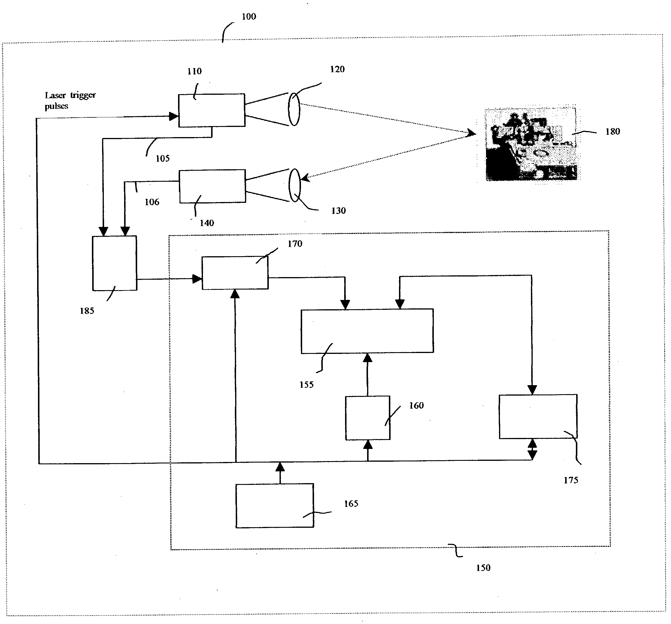
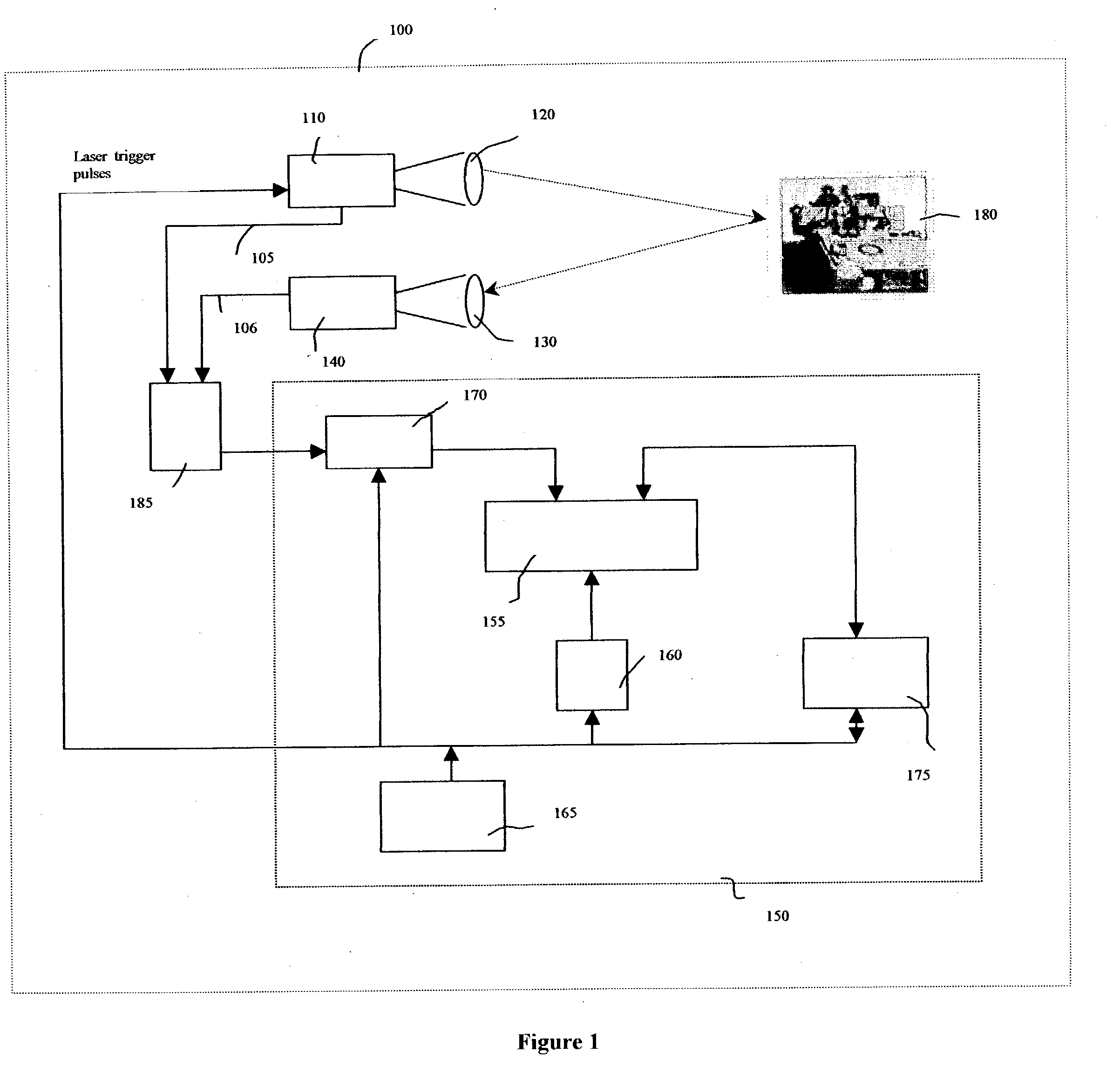
[0051]The present invention is directed toward systems for conducting laser range and enabling optical communication between a plurality of entities and to the application of such systems in a secure covert combat identification system. In one embodiment, the present invention uses a novel laser system that generates high pulse rates, as required for optical communications, while concurrently generating sufficiently high power levels, as required by laser range finding operations. One application of the present invention is in enabling secure covert communications between a plurality of parties. Another application of the present invention is in tracking and identifying the movement of objects. The present invention will be described with reference to aforementioned drawings. One of ordinary skill in the art would appreciate that the applications described herein are examples of how the broader concept can be applied.

Integrated Laser Range Finding and Optical Communications

[0052]Ref...


PUM


Abstract

The present invention is directed toward systems for conducting laser range and enabling optical communication between a plurality of entities and to the application of such systems in a secure covert combat identification system. In one embodiment, the present invention uses a novel laser system that generates high pulse rates, as required for optical communications, while concurrently generating sufficiently high power levels, as required by laser range finding operations. One application of the present invention is in enabling secure covert communications between a plurality of parties. Another application of the present invention is in tracking and identifying the movement of objects.

Description

CROSS-REFERENCE TO RELATED APPLICATIONS[0001]This invention is a continuation-in-part of co-pending application Ser. No. 10 / 066,099, having a priority date of Feb. 1, 2002, entitled “A Secure Covert Combat Identification Friend-or-Foe (IFF) System for the Dismounted Soldier”.FIELD OF THE INVENTION[0002]The present invention relates to optical systems, and, more specifically, to systems for conducting laser range and enabling optical communication between a plurality of entities and to the application of such systems in secure covert combat identification systems and object tracking systems.BACKGROUND OF THE INVENTION[0003]For various applications, including surveying, engaging in combat, and tracking objects, it is often necessary to determine the distance of remotely located objects and to communicate with a third party that may be proximate to the remotely located object. Conventionally, such functionality has been achieved using two separate systems that have been either physical...

Claims


Application Information

Patent Timeline
IPC IPC(8): H04B10/08G01S17/86G01S7/481G01S7/484G01S17/10G01S17/74
CPCG01S7/481G01S7/484G01S17/023G02B26/0841G01S17/74H04B10/1123G01S17/10G01S17/86
Inventor VARSHNEYA, DEEPAKROES, JOHN
Owner CUBIC CORPORATION
Why Eureka
Try Eureka