Digital x-ray detectors

a detector and digital technology, applied in the field of digital x-ray detectors, can solve the problems of x-ray detector design, relative heavy and thick x-ray detector,

Active Publication Date: 2009-01-15
GENERAL ELECTRIC CO
View PDF19 Cites 38 Cited by
  • Summary
  • Abstract
  • Description
  • Claims
  • Application Information

AI Technical Summary

Benefits of technology

[0007]Briefly in accordance with one aspect of the present technique, an x-ray detector is provided. The x-ray detector includes a detector subsystem configured to output electrical signals in response to reception of x-rays. The detector subsystem includes an imaging panel, a support layer and a low density core disposed between the imaging panel and the support layer.
[0008]In accordance with another aspect of the present technique, an x-ray detector is provided. The x-ray detector includes a detector subsystem configured to output electrical signals in response to reception of x-rays. The detector subsystem includes an imaging panel comprising a two-dimensional flat panel substrate. The detector subsystem further includes a low density core disposed over a support layer and bonded to the two-dimensional flat panel substrate such that the low density core is sandwiched between the two-dimensional flat panel substrate and the support layer.
[0009]In accordance with a further aspect of the present technique, an x-ray detector is provided. The x-ray detector includes a detector subsystem configured to output electrical signals in response to reception of x-rays. The detector subsystem includes an integrated imaging panel and panel support having a two-dimensional flat panel substrate bonded to a low density core disposed over a support layer such that the low density core is sandwiched between the two-dimensional flat panel substrate and the support layer.

Problems solved by technology

Since the imaging panel is fragile, it must therefore be mechanically supported, by some type of panel support, during use.
Thus, the conventional construction of x-ray detectors results in a relatively heavy and thick x-ray detector.
This is particularly problematic for portable x-ray detector designs where a thin and lightweight assembly is desired.
However, the relatively thick and heavy panel support and external enclosure is required to protect the sensitive and fragile imaging components and the readout electronics as these portable detectors are typically used in environments where they can be dropped, impacted with a rigid object, or subjected to a patient load, e.g., placed directly beneath a patient being imaged.

Method used


Image

  • Digital x-ray detectors
  • Digital x-ray detectors
  • Digital x-ray detectors

Examples


Embodiment Construction

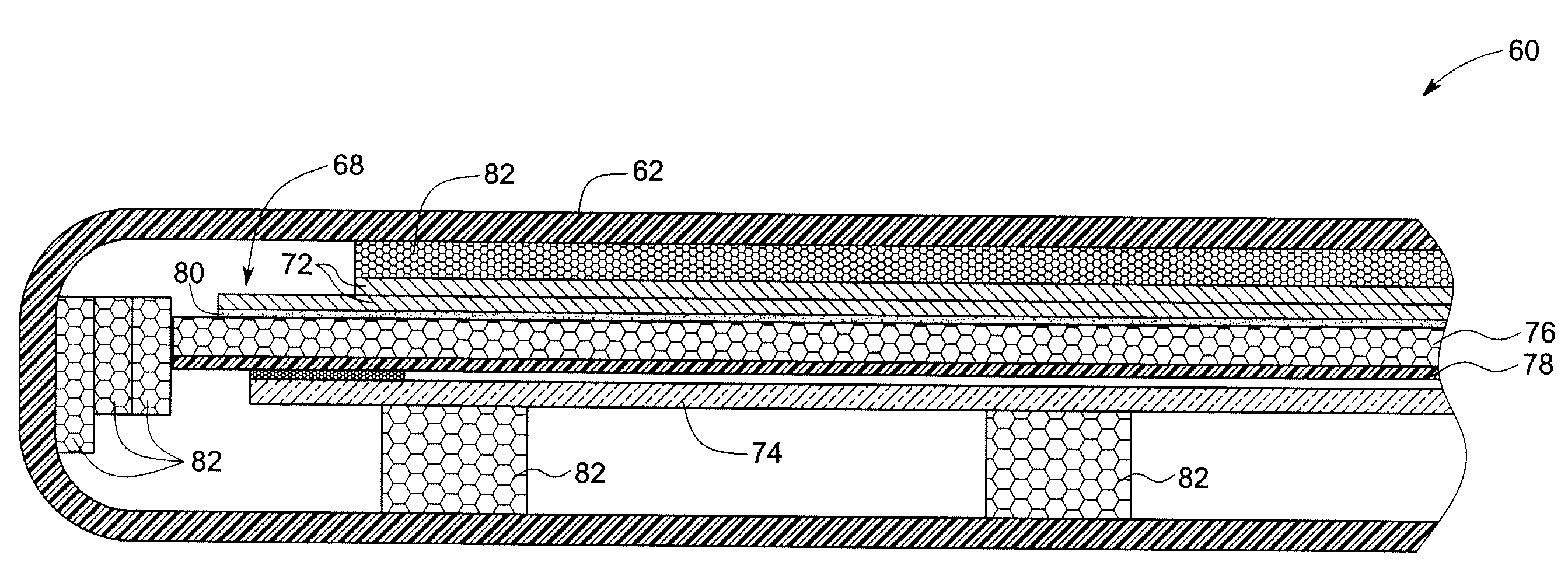
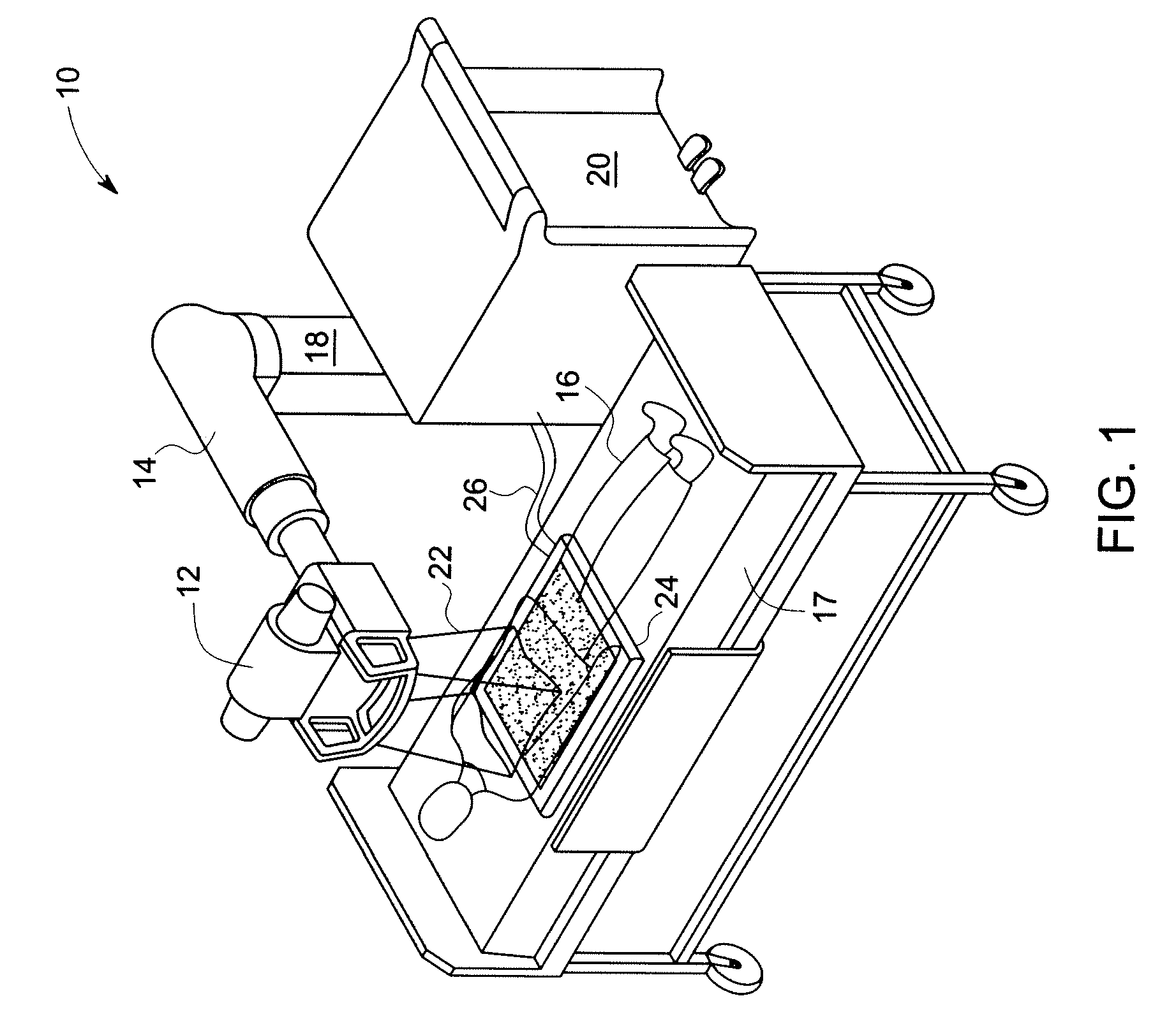
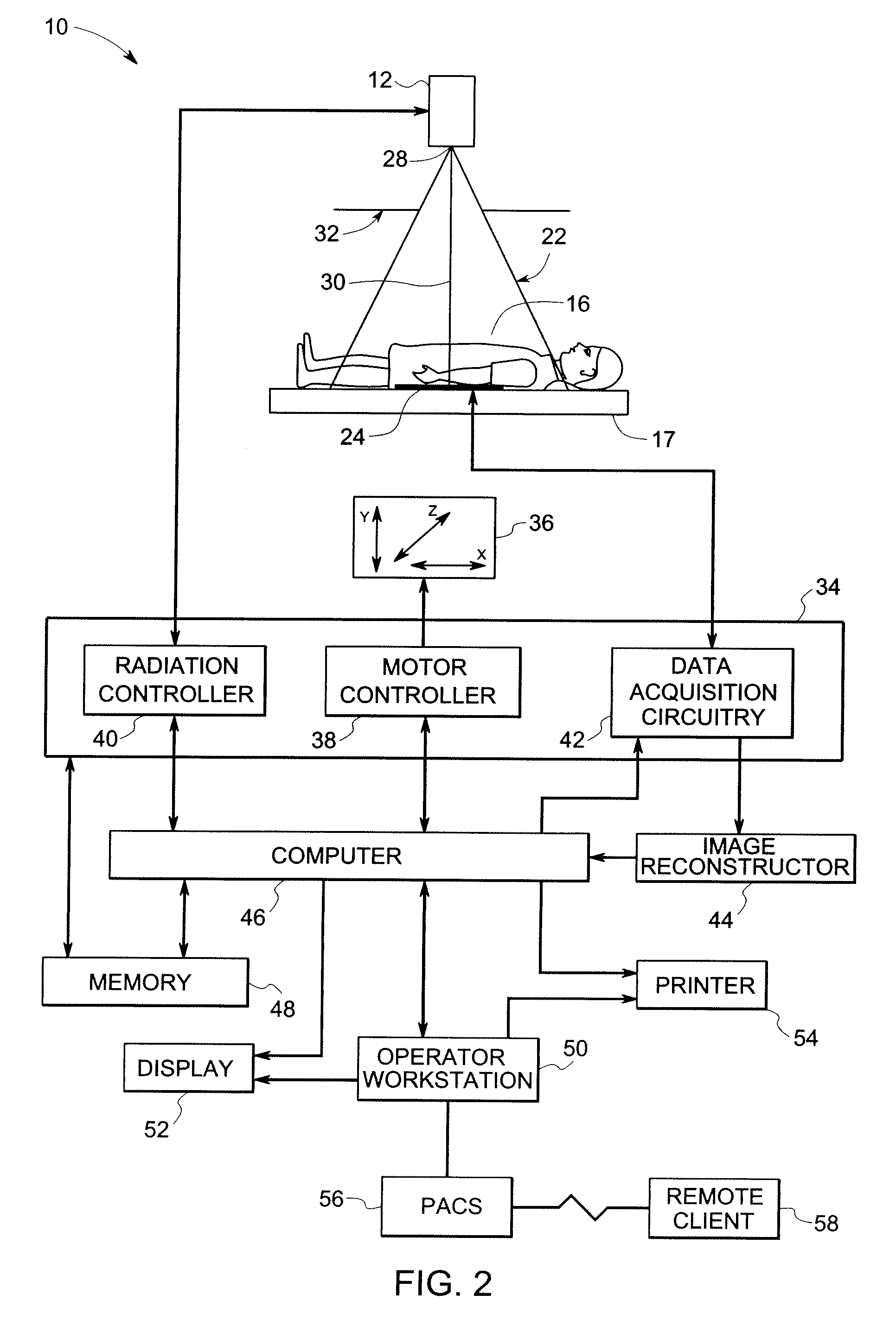
[0018]The present technique is generally directed to portable digital x-ray detectors. Generally, these detectors may be used in a variety of imaging systems, such as for medical imaging, industrial imaging, and baggage or package screening. Though the present discussion provides examples in a medical imaging context, one of ordinary skill in the art will readily comprehend that the application of these detectors in other contexts, such as for industrial imaging, security screening, and / or baggage or package inspection, is well within the scope of the present technique.

[0019]The present invention will be described with respect to a digital flat panel, solid-state, indirect detection, portable x-ray detector for use with a mobile x-ray imaging system. However, the present invention is equivalently applicable with other types of x-ray detectors including direct detection digital detectors. Additionally, the present invention may be used with stationary or fixed room x-ray imaging syst...


PUM


Abstract

An x-ray detector is provided for use in imaging systems. The x-ray detector includes a detector subsystem configured to output electrical signals in response to reception of x-rays. The detector subsystem includes an imaging panel, a support layer and a low density core disposed between the imaging panel and the support layer.

Description

BACKGROUND[0001]The invention relates generally to digital x-ray detectors and, more particularly, to x-ray detector panels having an integral panel support for use in digital x-ray detectors.[0002]Imaging systems are utilized for various applications in both medical and non-medical fields. For example, medical imaging systems include general radiological, mammography, x-ray C-arm, tomosynthesis, and computed tomography (CT) imaging systems. These various imaging systems, with their different respective topologies, are used to create images or views of a patient for clinical diagnosis based on the attenuation of radiation (e.g., x-rays) passing through the patient. Alternatively, imaging systems may also be utilized in non-medical applications, such as in industrial quality control or in security screening of passenger luggage, packages, and / or cargo. In such applications, acquired data and / or generated images representing volumes or parts of volumes (e.g., slices) may be used to de...

Claims


Application Information

Patent Timeline
Patent Type & Authority Applications(United States)
IPC IPC(8): G01T1/16
CPCG01T1/2018G03B42/04G01T1/20189G01T1/20184
Inventor HENNESSY, WILLIAM ANDREWVAFI, HABIBCASTLEBERRY, DONALD EARLUTSCHIG, MICHAEL JOHNBALASUBRAMANIAM, MAHADEVANJIANG, JIEGAIKWAD, VIRENDRA VILASACHUTHAN, AJITYAN, LE
Owner GENERAL ELECTRIC CO
Why Eureka
Try Eureka