
Eureka
For R&D, Eureka makes reading and utilizing patents & technical documents easy.
Eureka AIR
Designed for self-driven R&D workflows. Generate viable solutions, solve complex R&D challenges, empower your innovation with AI.

Eureka Materials
Designed for material experts only. Revolutionize your material R&D, from search, analyze, to developing new materials.

TechResearch
Generate reliable direction feasibility study reports for your R&D in just a few steps.

TechSeek
Discover and master advanced knowledge NOW. Basics, ideas, possibilities, all at once.

TechMind
As an expert in R&D Theories, TechMind can generates customized viable solutions instantly.

TechRisk
Analyze your overall solution with one click, know your potential R&D risks in advance.

TechMonitor
Get weekly tech updates, stay abreast of the latest tech innovations and key insights.
Inkjet recording apparatus
- Summary
- Abstract
- Description
- Claims
- Application Information
AI Technical Summary
Benefits of technology
Problems solved by technology
Method used
Image

Examples
first exemplary embodiment
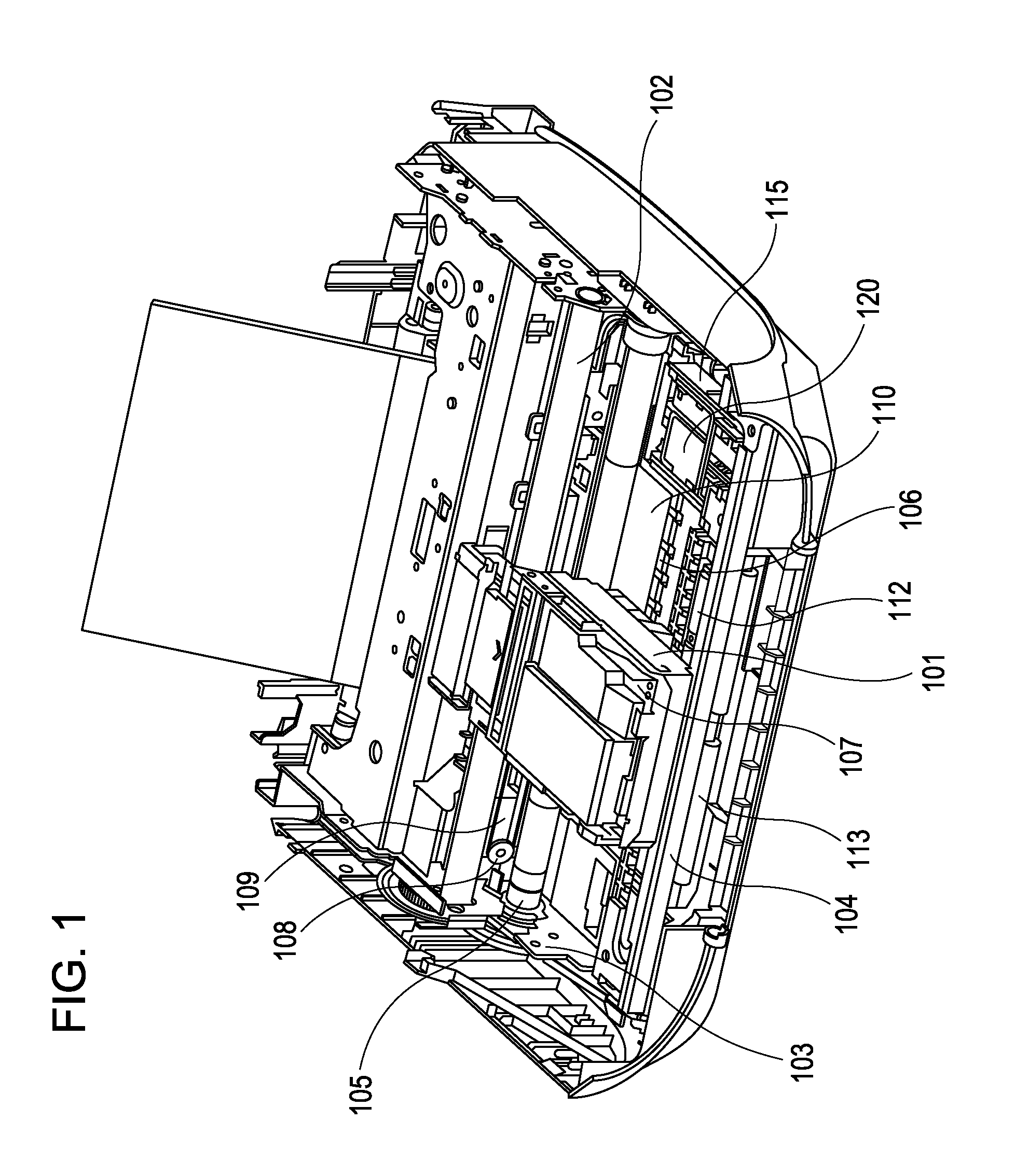
[0022]Embodiments of the present invention will now be described with reference to the accompanying drawings. Like reference numerals refer to like parts or corresponding parts throughout the various views. FIG. 1 is a perspective view of an inkjet recording apparatus suitable for embodying the present invention. In FIG. 1, a carriage 101 carries a recording head 107 and is supported in a manner capable of reciprocating along a guide shaft 102 and a guide rail 104. The carriage 101 is driven by a driving force from a carriage motor 108 transmitted through a belt 109. A recording medium 110 is conveyed through the nip of a conveying roller 105 and a pinch roller (not shown) to a platen 106, where the recording medium 110 faces the recording head 107. The guide shaft 102 and the conveying roller 105 are supported by a chassis 103. An eject roller 113 is provided downstream of the platen 106 with respect to the conveying direction of the recording medium 110. An auxiliary roller 112 is...
second exemplary embodiment
[0032]FIGS. 8A to 8C are side views of a cap unit according to a second embodiment, wherein FIG. 8A shows a state in which a cap 221 is in contact with the ejection orifice surface 151, FIG. 8B shows a state in which the cap 221 begins to be separated from the ejection orifice surface 151, and FIG. 8C shows a state in which the cap 221 has been removed from the ejection orifice surface 151. As shown in FIGS. 8A to 8C, the cap 221 has a first engaging portion 224a and a second engaging portion 224b that project from the side surfaces thereof. The first engaging portion 224a is provided at a position corresponding to the second contact portion 160. In the capped state, the top surface of the first engaging portion 224a is closer to the ejection orifice surface 151 than the top surface of the second engaging portion 224b. A cap holder 222 has a first retainer portion 225a and a second retainer portion 225b engageable with the engaging portions 224a and 224b, respectively. When the abov...
third exemplary embodiment
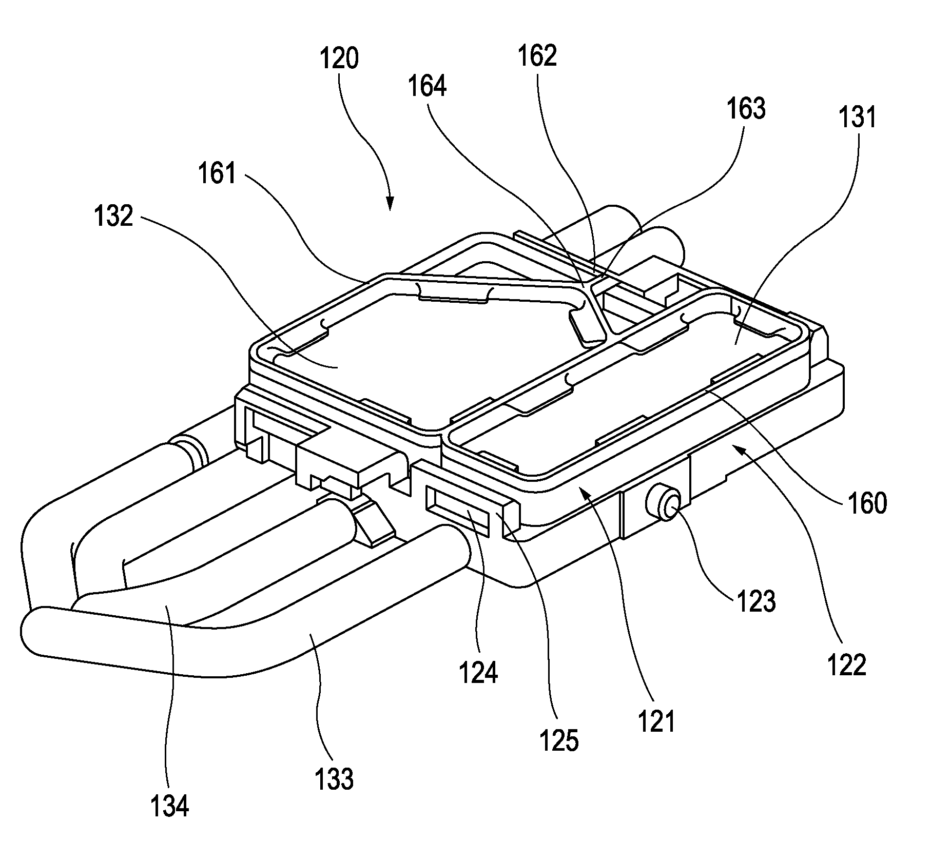
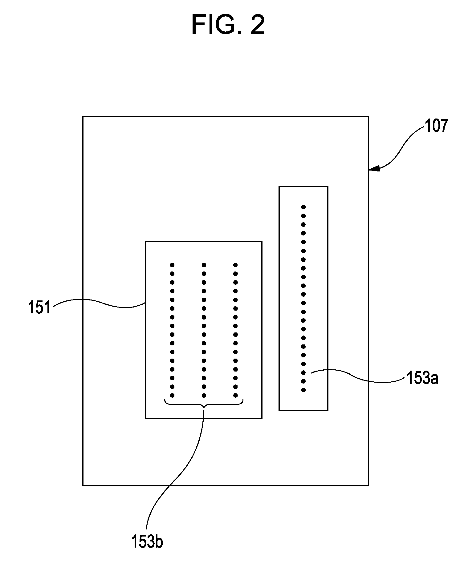
[0033]FIG. 9 is a plan view of a cap unit according to a third embodiment. The present embodiment is characterized by a second contact portion arranged parallel to the moving direction of the carriage. In FIG. 9, a cap 321 is provided to cover the ejection orifices by being brought into contact with the ejection orifice surface 151 of the recording head 107. A cap holder 322 retains the cap 321. The cap 321 has a black contact portion 360 configured to seal the black-ink ejection orifice row 153a by being pressed against an ejection orifice surface 151, a first contact portion 361 configured to seal the color-ink ejection orifice rows 153b, and a second contact portion 362 connected to the outer surface of the first contact portion 361, configured to be pressed against the ejection orifice surface 151. The second contact portion 362 is arranged parallel to the moving direction of the carriage 101 that reciprocates while carrying the recording head 107, as described above.
[0034]The s...
PUM
 Abstract
Description
Claims
Application Information
 - R&D Engineer
- R&D Manager
- IP Professional
- Industry Leading Data Capabilities
- Powerful AI technology
- Patent DNA Extraction
Browse by: Latest US Patents, China's latest patents, Technical Efficacy Thesaurus, Application Domain, Technology Topic, Popular Technical Reports.
© 2024 PatSnap. All rights reserved.Legal|Privacy policy|Modern Slavery Act Transparency Statement|Sitemap|About US| Contact US: help@patsnap.com