Wireless system, base station and mobile station

a wireless system and mobile station technology, applied in the field of wireless systems, to achieve the effect of reducing the jittering of packet sending and sending

Inactive Publication Date: 2009-01-15
HITACHI LTD
View PDF4 Cites 11 Cited by
  • Summary
  • Abstract
  • Description
  • Claims
  • Application Information

AI Technical Summary

Benefits of technology

[0010]And this problem arises not only in the sending in the forward link (FL) as shown in the example in FIG. 2, but also in the sending in the reverse link (RL). It is therefore an object of the present invention to reduce occurrence of packet sending delays, as well as occurrence of packet sending delay jittering at the time of hand-over processings.
[0011]Generally, packet sending delay jittering can be eliminated by adjusting the time interval of packets in the buffer at the receiver side of the subject sending block. This adjustment means changing delay types from variable delay to fixed delay. If an amount of delay jittering to be eliminated increases, the fixed delay to be added also comes to increase. Furthermore, as the added fixed delay increases, a required buffer capacity increases. In real time communications, sending delay and buffer capacity should preferably be suppressed to the minimum requirement. And another object of the present invention is to minimize such sending delay and buffer capacity.
[0013]Due to this exchange of messages required for the hand-over procedure, the timing of information burst sending to a wireless medium is prevented from bad influences that might otherwise be exerted from such message exchanges.
[0015]Consequently, the timing of information burst sending to the wireless medium is prevented from bad influences that might otherwise be exerted from such message exchanges.
[0017]According to an aspect of the present invention, therefore, the buffer capacity is changed at each of AT and AP and the scheduling method is changed at AP dynamically at the time of hand-over occurrence that might cause an increase of delay jittering occurrence, thereby the occurrence of packet sending delay jittering is reduced.

Problems solved by technology

However, because the predetermined hand-over procedure takes much time, the AP2 comes to receive packets E, F, and G collectively, then receive the subsequent packets H, I, .

Method used


Image

  • Wireless system, base station and mobile station
  • Wireless system, base station and mobile station
  • Wireless system, base station and mobile station

Examples


Embodiment Construction

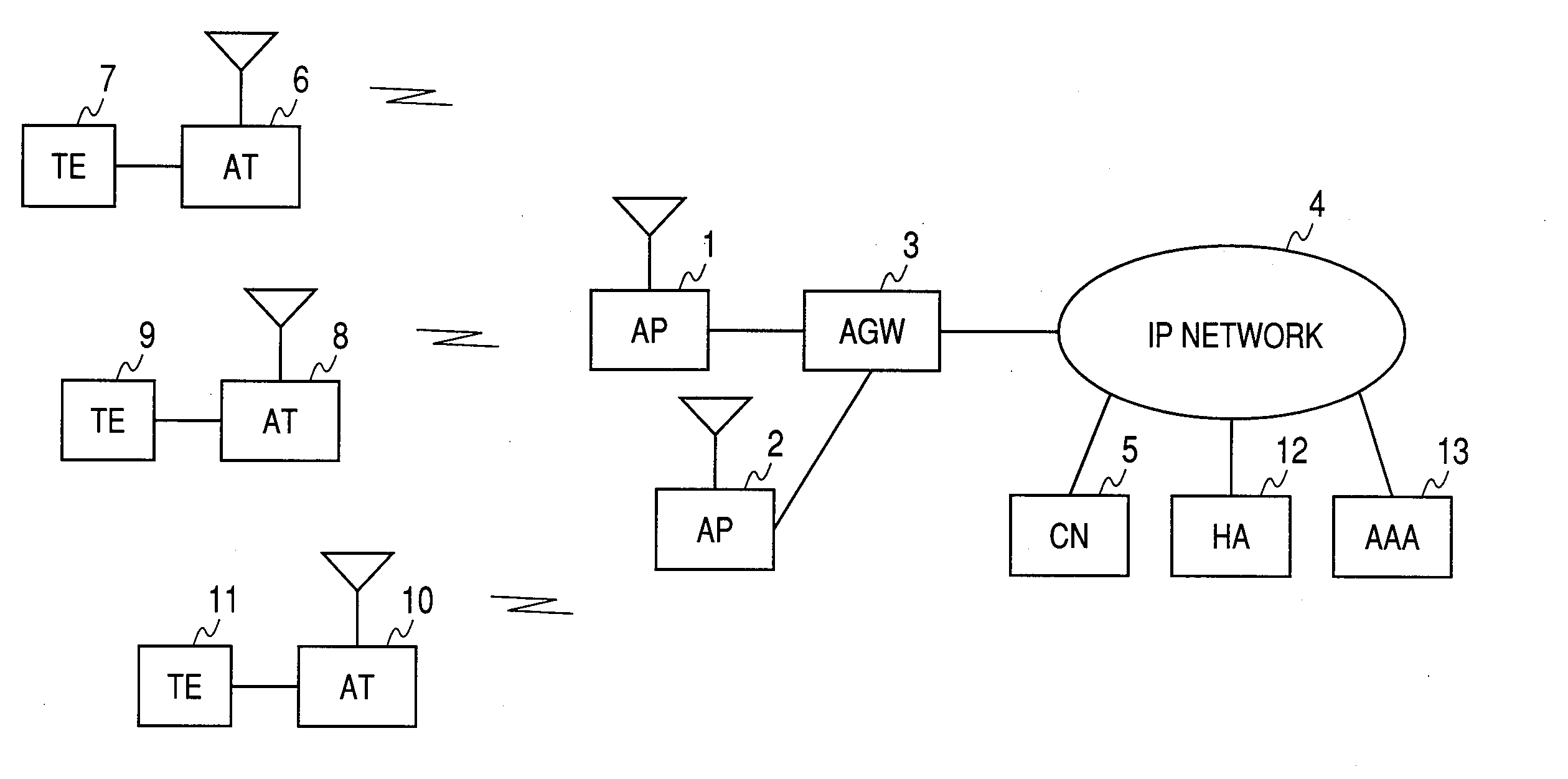
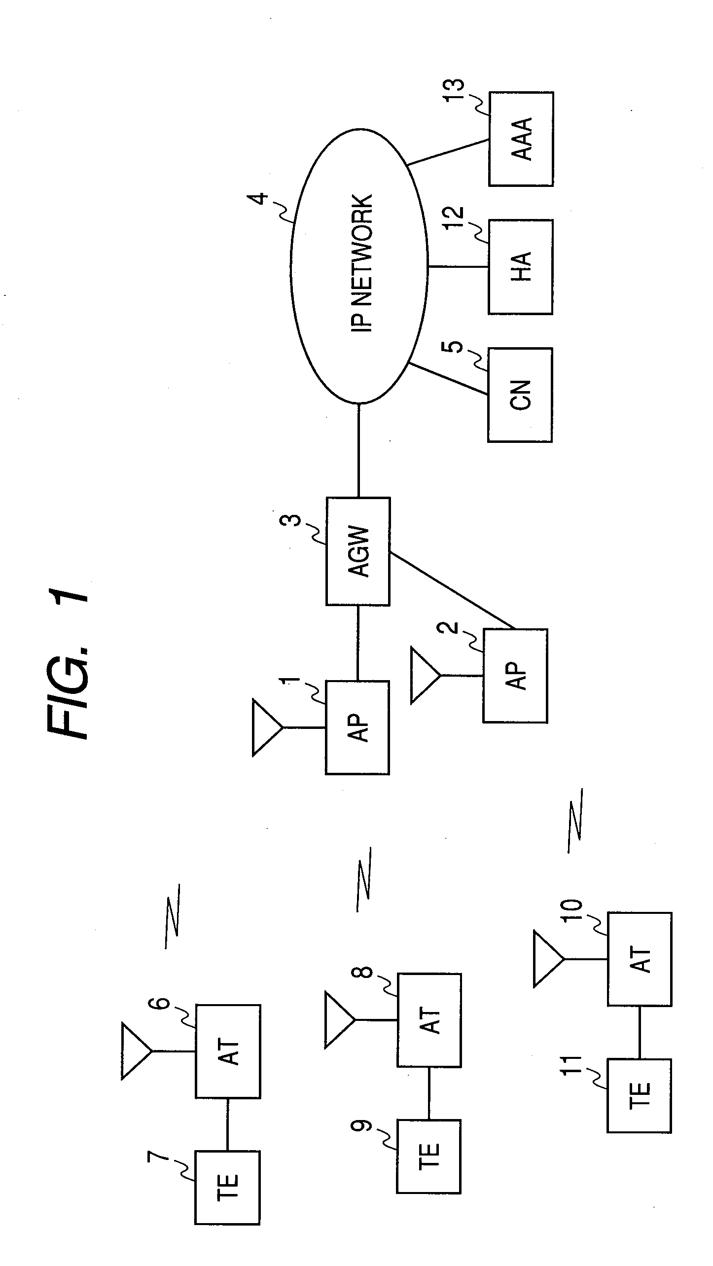
[0036]Hereunder, there will be described a wireless system, a base station, and a mobile station in the preferred embodiments of the present invention in detail with reference to the accompanying drawings.

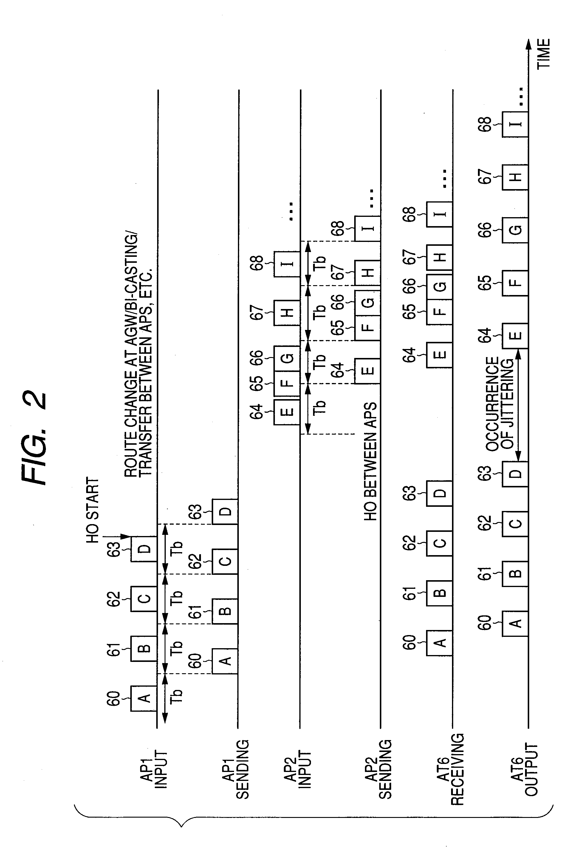
[0037]This wireless system is used for packet communication hand-over from a mobile station to another among a plurality of base stations. Each of the mobile stations and base stations includes a storage unit that holds packets and a unit that generates an information burst from those packets held in the storage unit. Each base station includes a unit that schedules information bursts sent from the base stations and mobile stations. Either the mobile station or the base station includes a unit that estimates hand-over occurrence and the base station changes the current scheduling method for the other if the unit estimates hand-over occurrence. And the plural base stations and their mobile stations exchange messages required for the hand-over procedure in a period between sending op...


PUM


Abstract

Disclosed herewith is a wireless system capable of reducing packet sending delay occurrence and packet sending delay jittering at the time of hand-over processing executed therein. In the wireless system, upon estimating occurrence of a hand-over event, a subject mobile station and its base station extend the packet buffering period respectively and furthermore, the base station changes the current burst scheduling method for another. The base station and the mobile station then exchanges messages required to execute the hand-over procedure in a period between when sending of a burst ends and when sending of the next burst begins.

Description

CLAIM OF PRIORITY[0001]The present application claims priority from Japanese application JP 2007-181608 filed on Jul. 11, 2007, the content of which is hereby incorporated by reference into this application.FIELD OF THE INVENTION[0002]The present invention relates to a wireless system employed for real time packet communications.BACKGROUND OF THE INVENTION[0003]In recent years, real time communications have widespread using means of VoIP (Voice over IP), TV phones, etc. in wireless system packet communication networks. Consequently, the traffics of such real time communications are now increasing more and more. On the other hand, as the functions of those wireless systems, such as QoS (Quality of Service) control, policy control, dynamic address assignment, authentication, etc. have been enhanced and complicated, the hand-over time have also been extended accordingly. Under such circumstances, keeping the real time communication quality even at such hand-over events is becoming one ...

Claims


Application Information

Patent Timeline
Patent Type & Authority Applications(United States)
IPC IPC(8): H04Q7/00H04W28/10H04W36/02H04W36/08H04W36/36H04W84/12H04W88/08
CPCH04W72/12H04W36/02
Inventor WATANABE, KOJITAKAHASHI, YOSUKE
Owner HITACHI LTD
Why Eureka
Try Eureka