Apparatus and method for biological sample processing

a biological sample and apparatus technology, applied in the direction of automatic control, process and machine control, instruments, etc., can solve the problems of inherently inconsistent techniques, reducing the extent to which such “lean” methods can increase workflow, and difficult for pathologists or other medical or research personnel to interpret samples and make comparisons between different samples

Active Publication Date: 2009-01-15
VENTANA MEDICAL SYST INC
View PDF46 Cites 52 Cited by
  • Summary
  • Abstract
  • Description
  • Claims
  • Application Information

AI Technical Summary

Benefits of technology

[0007]A biological sample processing apparatus is disclosed. In one embodiment, the apparatus includes a plurality of substrate holders where each substrate holder is automatically and independently movable between a different processing position and a different access position, and a moveable sample processor configured to simultaneously process two or more substrates held on two or more substrate holders in their different processing positions. In particular embodiments, the apparatus is configured to independently process each of a plurality of samples in a manner that permits samples to be individually added or retrieved from the system without interrupting the processing of other samples in the apparatus. A particular advantage of the disclosed system is its compatibility with lean work-flow methods for sample processing, such as pacing sample processing with sample preparation.

Problems solved by technology

These techniques are inherently inconsistent when performed manually, especially by multiple different persons.
Inconsistent staining makes it difficult for a pathologist or other medical or research personnel to interpret samples and to make comparisons between different samples.
However, constraints imposed by currently available sample processors, and in particular batch sample processors, reduce the extent to which such “lean” methods can increase workflow.

Method used


Image

  • Apparatus and method for biological sample processing
  • Apparatus and method for biological sample processing
  • Apparatus and method for biological sample processing

Examples


example 1

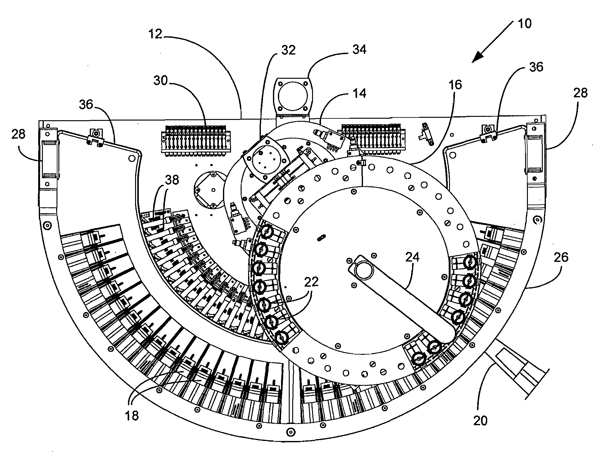
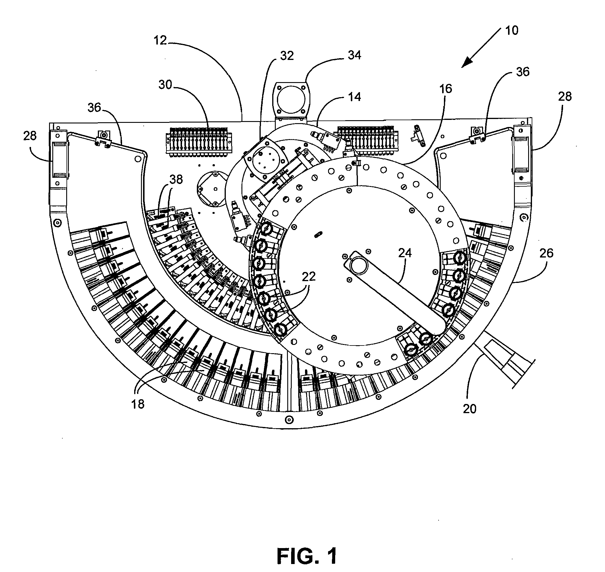
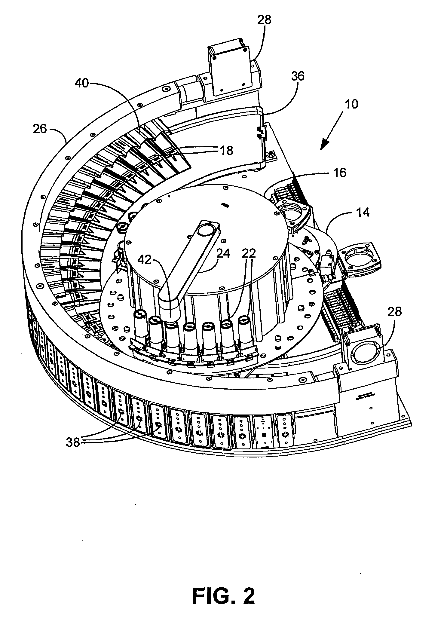
Biological Sample Processing Unit

[0051]Various prior staining instruments have been of a batch architecture, where a batch of microscope slides is processed together. The batch size can vary but all slides in a batch are processed as a group, and more particularly as a group having common processing steps that are shared amongst the batch of slides. A batch instrument has several disadvantages relating to how it disrupts the flow of work through a laboratory. For example, the instrument cannot be started until a full batch of similar slides become available, otherwise to run less than a full batch sacrifices the instrument's capacity. This means that slides that are ready to be stained early in the day must wait until there are enough slides available to make the run efficient, delaying patient results that are so important when a patient has learned they may have a serious medical condition. Another disadvantage of batching results from the fact that the time to finish different pr...

example 2

Railed Sample Aspirator Unit

[0070]In one embodiment, a railed sample aspirator unit is utilized to remove residual reagents from a substrate. The railed aspirator unit can include discrete rails (see, for example, U.S. Patent Application Publication 2006 / 0019303, which is incorporated by reference herein) and can further include reagent dispensing means. However, in the particular embodiment discussed in this Example, an improvement to such a system is disclosed that allows the aspirator head to use the substrate as a reference surface for accurately controlling the gap between the head and the top surface of the substrate without disturbing a sample on the top surface of the substrate. A second improvement is to have two sets of vacuum holes, one pulling liquid from the small gap that is formed between the bottom of the vacuum head and the top of the substrate and the other set pulling liquid from the top of the puddle that builds in front of the advancing head as is moves out over...

example 3

Radiant Thermal Control Unit

[0076]Certain substrate processing steps utilized in immunohistochemical (IHC) and in situ hybridization (ISH) analyses (for example, cell conditioning, antigen retrieval, target retrieval, nucleic acid denaturation, nucleic acid hybridization and the like) have increased the desirability of achieving higher and more accurate sample temperatures. Conductive heating suffers from several drawbacks when attempting to elevate the temperature of a substrate and a sample thereon, particularly when attempting to elevate the temperature above about 80° C. and more particularly above about 100° C. Ideally, the temperature of the heater and the temperature of a substrate touching the heater are identical, but any gap between the heater surface and the substrate presents resistance to heat flow and causes different parts of the substrate to have different temperatures. The thermal resistance across a substrate depends on heater and substrate flatness and whether any...


PUM

PropertyMeasurementUnit
outer radiusaaaaaaaaaa

Abstract

An apparatus and method are described that achieve independent and simultaneous processing of a plurality of substrate-supported biological samples. In one embodiment, substrate holders arranged in a minor arc are independently moveable between a processing position and an access position, and reagents are delivered to substrates held in the substrate holders through a nozzle plate that moves along the arc of substrate holders. The disclosed apparatus and method are particularly suited for implementation of lean processing of biological samples.

Description

RELATED APPLICATION DATA[0001]This claims the benefit of U.S. Provisional Patent Application No. 60 / 958916, filed Jul. 10, 2007, which application is incorporated by reference herein.BACKGROUND OF THE INVENTION[0002]1. Field[0003]The present invention relates to equipment and methods for preparing samples for analysis. In particular, the invention relates to equipment and methods for automated processing of biological samples on substrates.[0004]2. Background[0005]Primary staining, special staining, immunochemical analyses, and in situ hybridization (ISH) analyses are utilized to analyze a variety of biological samples including microarray samples, tissue samples and tissue array samples. These techniques are inherently inconsistent when performed manually, especially by multiple different persons. Inconsistent staining makes it difficult for a pathologist or other medical or research personnel to interpret samples and to make comparisons between different samples. Thus, a number of...

Claims


Application Information

Patent Timeline
Patent Type & Authority Applications(United States)
IPC IPC(8): G01N1/30B01J19/00G01N1/28G05B11/00G01N25/00
CPCG01N35/00029G01N35/0092G01N35/1081G01N2035/00138G01N2035/00376G01N35/1011Y10T436/2575G01N1/312G01N2035/0453G01N2035/00049G01N1/06Y10T436/25Y10T436/112499G01N35/1002G01N2035/00039G01N2035/00346
Inventor LEMME, CHARLES D.RICHARDS, WILLIAMWARD, GLENASHBY, AUSTINGHUSSON, ANDREWJENSEN-LONG, LISAKNAPP, KEVINKUGIZAKI, RODNEYLARSON, ALAINRICHARDS, PAULSHOWALTER, WAYNEWILKINSON, CHAD
Owner VENTANA MEDICAL SYST INC
Why Eureka
Try Eureka