
Landing ladder

a technology for landing ladders and ladders, applied in the direction of vehicle components, steps, constructions, etc., can solve the problems of user discomfort, unacceptable solutions, and treads or steps, and achieve the effect of eliminating pinch points

Inactive Publication Date: 2009-01-22
ROM ACQUISITION CORP
View PDF4 Cites 38 Cited by
  • Summary
  • Abstract
  • Description
  • Claims
  • Application Information

AI Technical Summary

Benefits of technology

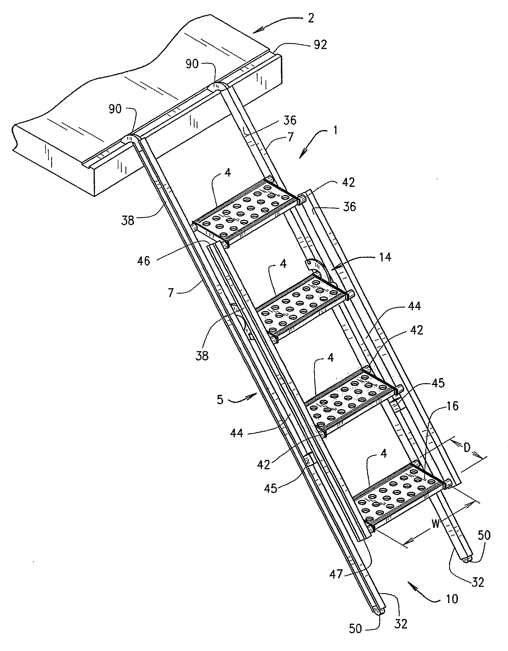
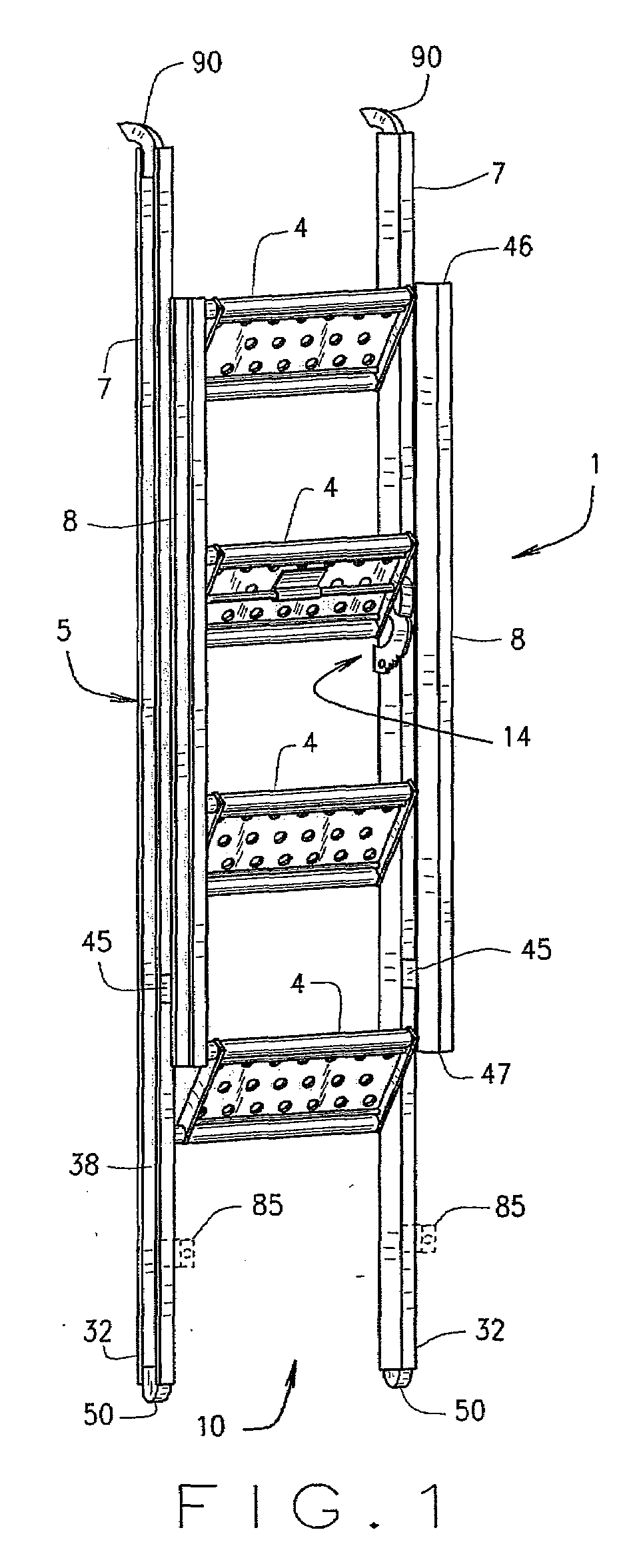
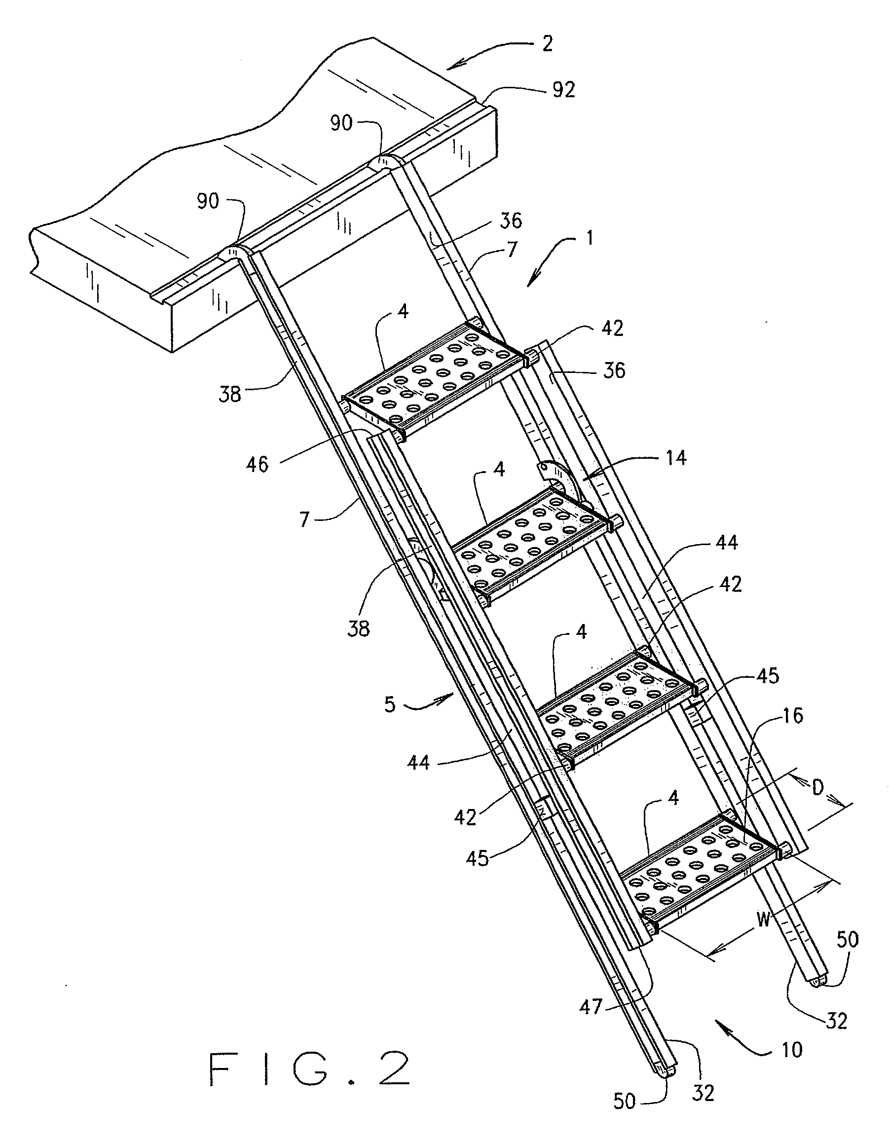
[0003]The present invention involves the provision of a collapsible ladder having adjustable pitch steps with at least one use pitch. The ladder includes at least one back rail connected to the steps which steps can selectively pivot relative to the back rail. At least one link is connected to the steps to help simultaneous pivoting movement of the steps relative to the back rail. A base is provided for engaging the ground and the base spans a substantial distance on the ground for stability. A stop mechanism is provided and is operably associated with the link and or steps to selectively limit movement of steps relative to the back rail to fix the pitch of the steps. The stop mechanism may include a ratchet mechanism and / or fixed stops. One or more spacers may also be provided to provide for a space between the link and the back rail to eliminate a pinch point.

Problems solved by technology

This presents problems with ladders having deep treads or steps since the treads or steps will not necessarily be at the correct and preferably level pitch.
Small depth and curved contact surfaces can cause user discomfort.
These solutions, however, have not been acceptable particularly when the ladder is to be used where deep treads are desirable for user comfort and stability.

Method used


Image

  • Landing ladder
  • Landing ladder
  • Landing ladder

Examples


Embodiment Construction

[0011]The reference numeral 1 designates generally a ladder for use with a vehicle or other device such as a landing 2 which may be part of a vehicle. The ladder 1 is useful with any vehicle, e.g., a vehicle used for transporting and distributing goods or items, an emergency vehicle such as a fire truck or an ambulance, a maintenance or service truck or the like, where on occasion, a user needs to move to an elevated position to perform acts such as loading and unloading, accessing supplies, equipment and the like. The ladder 1 includes a plurality of steps or treads 4 that are supported by a suitable support structure 5 permitting pivoting movement of the steps 4 on the support structure. The support structure 5, in the illustrated embodiment, includes at least one back rail 7 and at least one link 8 each connected to each of the steps 4. A landing (not shown) may also be provided as part of the ladder 1, if desired, which would be particularly useful when the ladder 1 is to be use...


PUM


Abstract

The present invention involves a selectively collapsible ladder which permits for adjusting the pitch of the steps between at least two pitches, one pitch being where the ladder collapsed for storage and another pitch whereby the steps are positioned for use by a user. The ladder includes a support structure comprising one or more support rails for extending between the ground and a loading or work surface or storage compartment. The steps are connected together by one or more links for effecting simultaneous movement of the steps. A stop mechanism is provided to releasably fix the step pitch relative to a support rail. The stop mechanism may include a ratchet mechanism that permits setting the pitch of the steps at one of several available pitch settings.

Description

BACKGROUND OF INVENTION[0001]In the operation of trucks and other vehicles, the use of a ladder therewith may be needed for the effective operation of the vehicle. Such vehicles may include trucks used for hauling goods or items, service vehicles, emergency vehicles e.g., fire trucks and emergency medical treatment vehicles. Such ladders are useful in assisting in loading and unloading items from a truck or obtaining access to various regions in a fire truck, ambulance or the like. The landing, door or other area of the vehicle that needs access is not always at the same height above the ground often times because of terrain or there may be multiple areas on a single vehicle that need accessed. This presents problems with ladders having deep treads or steps since the treads or steps will not necessarily be at the correct and preferably level pitch. One solution to this problem is the use of ladders with rungs that have a small depth so that the out of pitch condition is not noticeab...

Claims


Application Information

Patent Timeline
IPC IPC(8): E06C1/38
CPCB60R3/02E06C5/02E06C1/387
Inventor MAY, BRIAN A.
Owner ROM ACQUISITION CORP
Learn More