Container End Closure With Improved Chuck Wall and Countersink

a technology of end closure and countersink, which is applied in the field of container and container end closure, can solve the problems of not using the standard double seaming process, the 634 patent has not proved to be completely reliable in regard to leakage, and the end closure of the beverage container is described, so as to reduce the size of the blank material, improve the strength of the end closure, and save material costs

Active Publication Date: 2009-01-22
BALL CORP
View PDF99 Cites 26 Cited by
  • Summary
  • Abstract
  • Description
  • Claims
  • Application Information

AI Technical Summary

Benefits of technology

[0008]In another aspect of the present invention, a container end closure is provided which is manufactured with conventional manufacturing equipment and thus generally eliminates the need for expensive new equipment required to make the beverage can container end closure. Thus, existing and well known manufacturing equipment and processes can be implemented to quickly and effectively initiate the production of an improved beverage can container end closure in an existing manufacturing facility, i.e., can plant.
[0010]In another aspect of the present invention, a beverage can end closure is provided with a countersink having an inner panel wall with a distinct non-linear, outwardly oriented radius of curvature of between about 0.025 inches and 0.080 inches. As referred to herein, the term “outwardly” refers to a direction oriented generally toward the container neck or sidewalls, while “inwardly” generally refers to a direction away from the container neck or sidewalls. Preferably, the curved portion of the inner panel wall is positioned just below the point of interconnection with the central panel, and has been shown to improve the strength of the end closure.
[0011]It is another aspect of the present invention to provide a beverage can end closure which saves material costs by reducing the size of the blank material and / or utilizing thinner materials which have improved aluminum alloy properties. Thus, the integrity and strength of the beverage can end closure is not compromised, while material costs are significantly reduced as a result of the blank reduction, and / or improved aluminum alloy properties provided therein.
[0014]It is yet a further aspect of the present invention to reduce the distance between the inner and outer panel walls of the countersink, and to thus save material costs while additionally improving the strength of the end closure. Thus, in one embodiment of the present invention the distance between the inner and outer panel walls is between about 0.045 inches and 0.055 inches, and more preferably about 0.052 inches.

Problems solved by technology

Unfortunately, the beverage container end closure described in the '634 Patent has not proven to be completely reliable with regard to leaking, and does not utilize standard double seaming processes which are well known and used in the industry.

Method used


Image

  • Container End Closure With Improved Chuck Wall and Countersink
  • Container End Closure With Improved Chuck Wall and Countersink
  • Container End Closure With Improved Chuck Wall and Countersink

Examples


Embodiment Construction

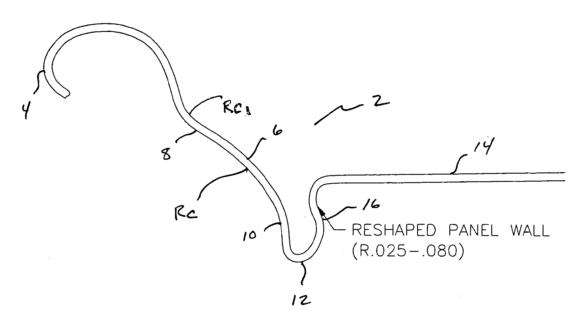
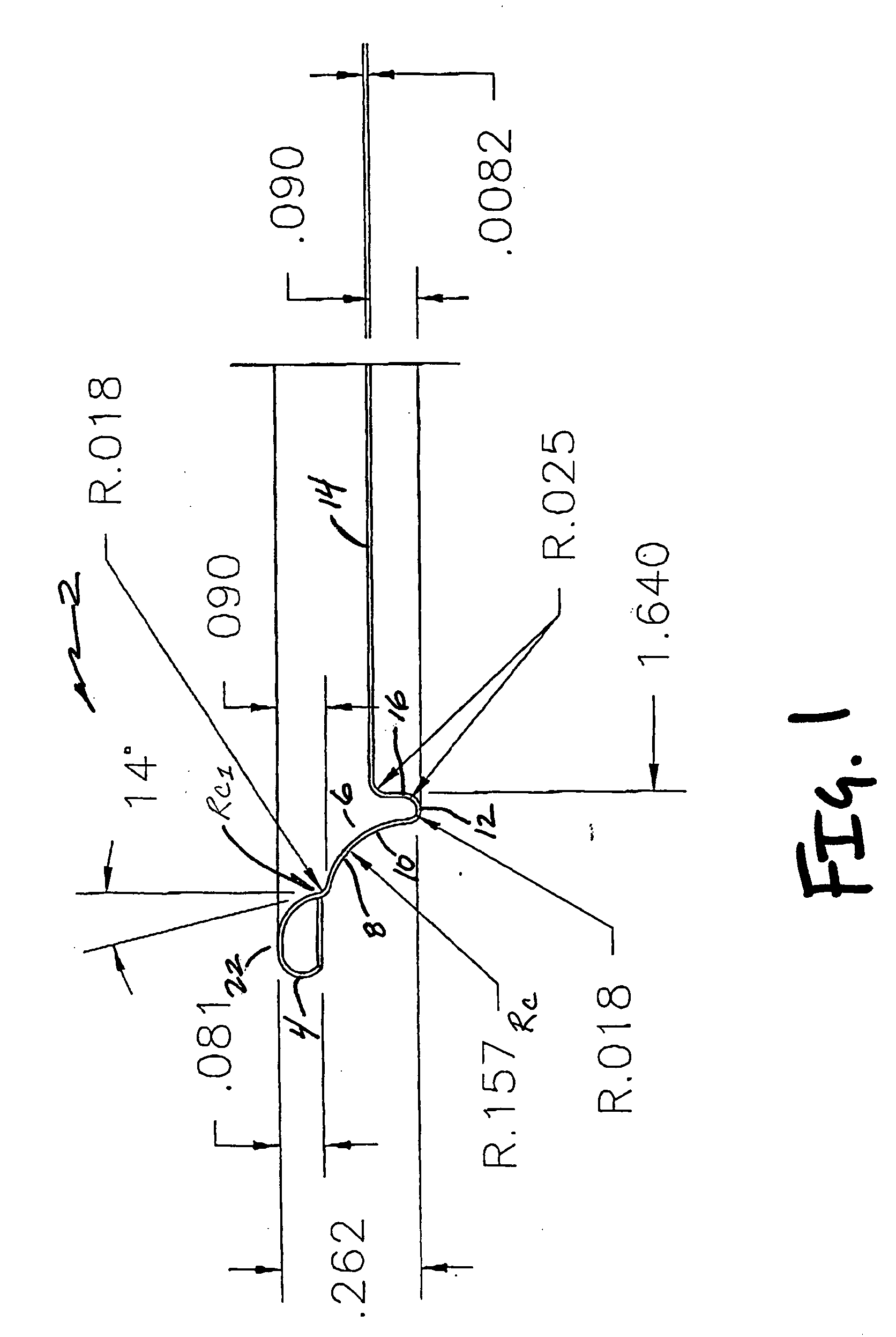
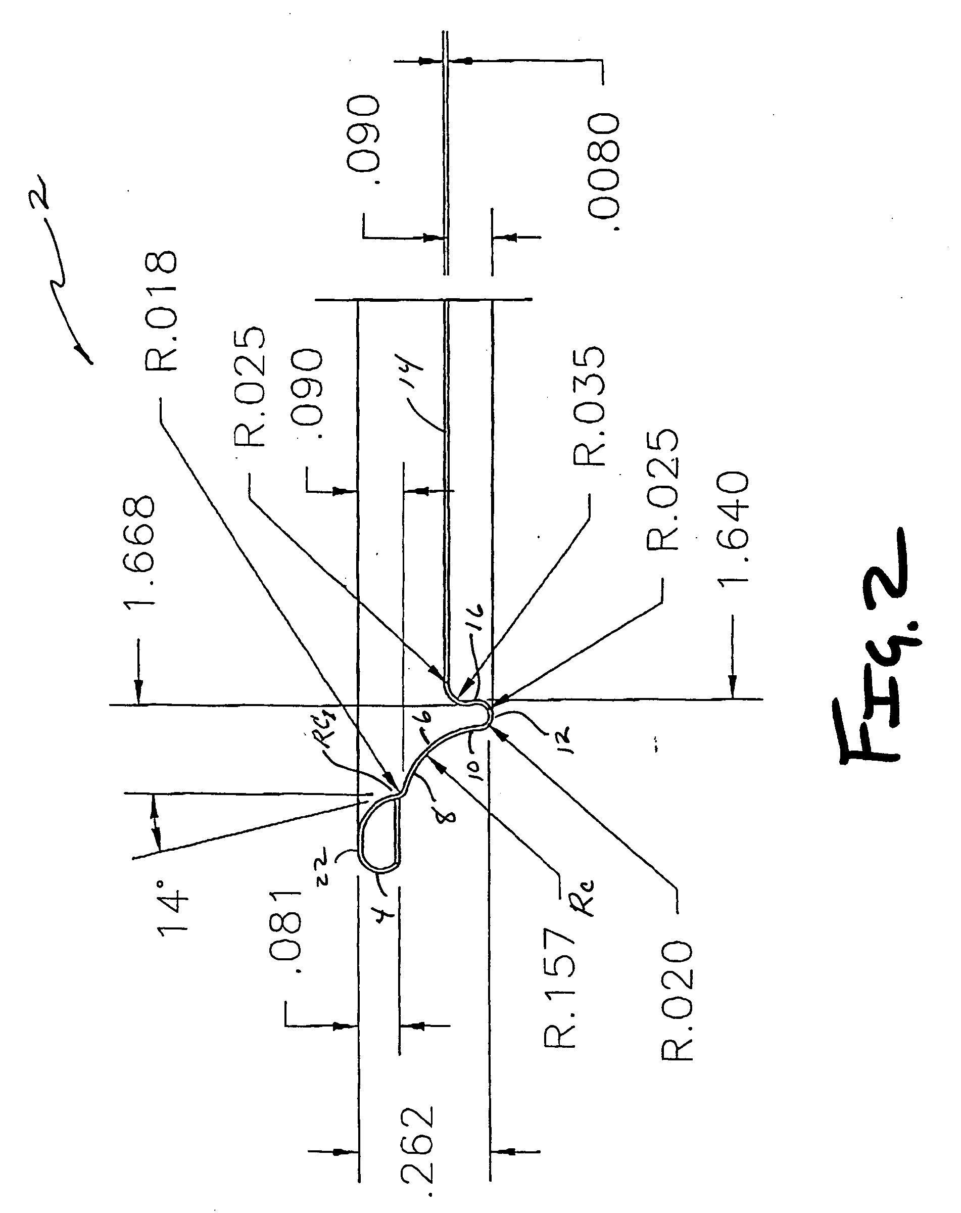
[0043]Referring now to the drawings, FIGS. 1-10 represent alternative embodiments of the present invention, and identifying various geometries which may be incorporated in a beverage can end closure 2 to achieve superior performance including buckle resistance. Each of the geometries shown in FIGS. 1-10 may be utilized independently, or alternatively combined in one or more combinations. FIGS. 11-13 represent prior at end closures 2, while FIGS. 14-19 depict cross-sectional front elevation views of alternative embodiments of the present invention. FIG. 20 shows a stacking arrangement of one end closure of the present invention and identifying the amount of “shuffle,” i.e. horizontal movement in a 2″ vertical stack of end closures. With regard to FIGS. 1-10, and the geometries provided herein, a detailed chart of these end closures is provided herein in the specification, wherein the specific geometry for each end closure is provided as well as specific performance data. Additionally...


PUM


Abstract

The present invention describes a beverage can end which utilizes less material and has an improved internal buckle strength based on the geometric configuration of a chuck wall, inner panel wall and central panel, and which, in one embodiment utilizes an arcuate shaped chuck wall with a radius of curvature between about 0.150 inches and 0.250 inches with at least one transition zone positioned between an upper and lower end of the chuck wall.

Description

[0001]This application is a Divisional of pending U.S. patent application Ser. No. 11 / 235,827, filed Sep. 26, 2005, which claims the benefit of U.S. Provisional Patent Application Ser. No. 60 / 613,988, filed Sep. 27, 2004, the entire disclosures of which being incorporated herein.FIELD OF THE INVENTION[0002]The present invention generally relates to containers and container end closures, and more specifically metallic beverage container end closures adapted for interconnection to a beverage can body.BACKGROUND OF THE INVENTION[0003]Containers and more specifically metallic beverage containers are typically manufactured by interconnecting a beverage can end closure on a beverage container body. In some applications, an end closure may be interconnected on both a top side and a bottom side of a can body. More frequently, however, a beverage can end closure is interconnected on a top end of a beverage can body which is drawn and ironed from a flat sheet of blank material such as aluminu...

Claims


Application Information

Patent Timeline
Patent Type & Authority Applications(United States)
IPC IPC(8): B65D6/30B21D51/38
CPCB65D7/04Y10S220/906B65D17/08B65D7/36
Inventor BULSO, JOSEPH D.
Owner BALL CORP
Why Eureka
Try Eureka