Power reception control device, power reception device, non-contact power transmission system, charge control device, battery device, and electronic instrument

a power reception device and control device technology, applied in the direction of exchanging data chargers, inductances, transportation and packaging, etc., can solve the problems of abnormal heat generation, limited functions, and inability of non-contact power transmission systems to positively control the charging current (charging voltage) supplied to the battery

Active Publication Date: 2009-01-22
SEIKO EPSON CORP
View PDF4 Cites 138 Cited by
  • Summary
  • Abstract
  • Description
  • Claims
  • Application Information

AI Technical Summary

Problems solved by technology

According to this configuration, the non-contact power transmission system cannot positively control the charging current (charging voltage) supplied to the battery.
Therefore, the functions that can be implemented are limited.
Specifically, when power is transmitted in a state in which a metal foreign object is present, abnormal heat generation may occur.
For example, when a t

Method used


Image

  • Power reception control device, power reception device, non-contact power transmission system, charge control device, battery device, and electronic instrument
  • Power reception control device, power reception device, non-contact power transmission system, charge control device, battery device, and electronic instrument
  • Power reception control device, power reception device, non-contact power transmission system, charge control device, battery device, and electronic instrument

Examples


first embodiment

[0139]Examples of an electronic instrument to which the invention is suitably applied and the principle of non-contact power transmission technology are described below.

[0140]Examples of Electronic Instrument and Principle of Non-Contact Power Transmission

[0141]FIGS. 1A to 1C are views illustrative of examples of an electronic instrument to which the non-contact power transmission technology is applied, and the principle of non-contact power transmission using an induction transformer.

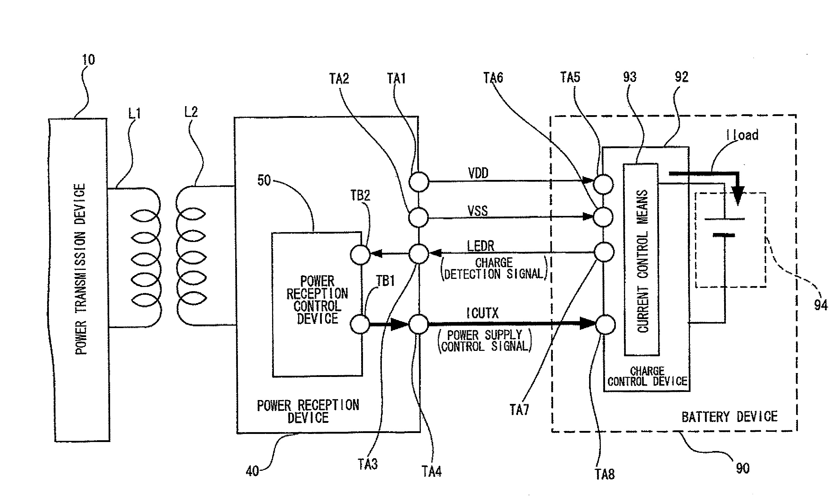
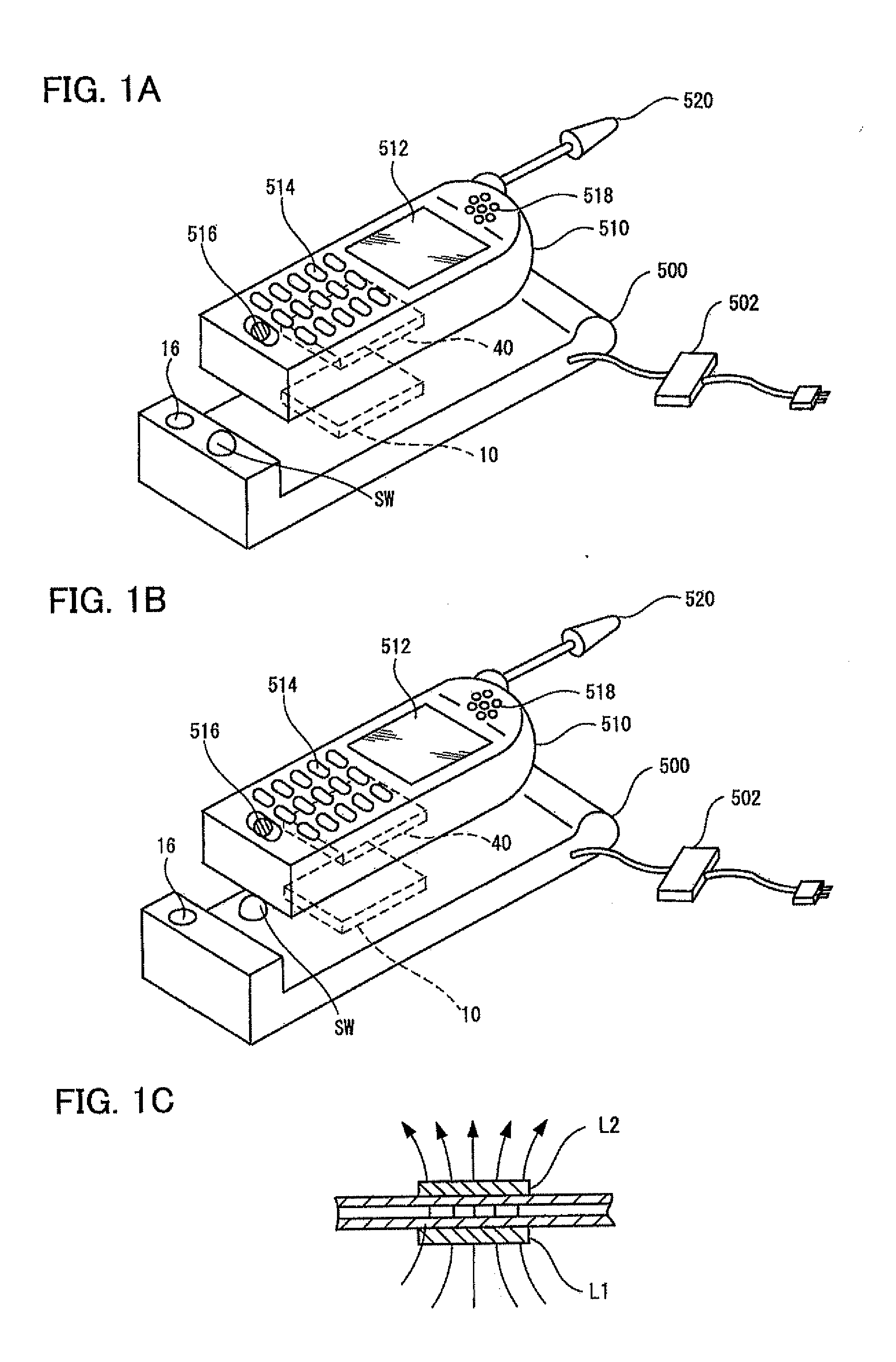
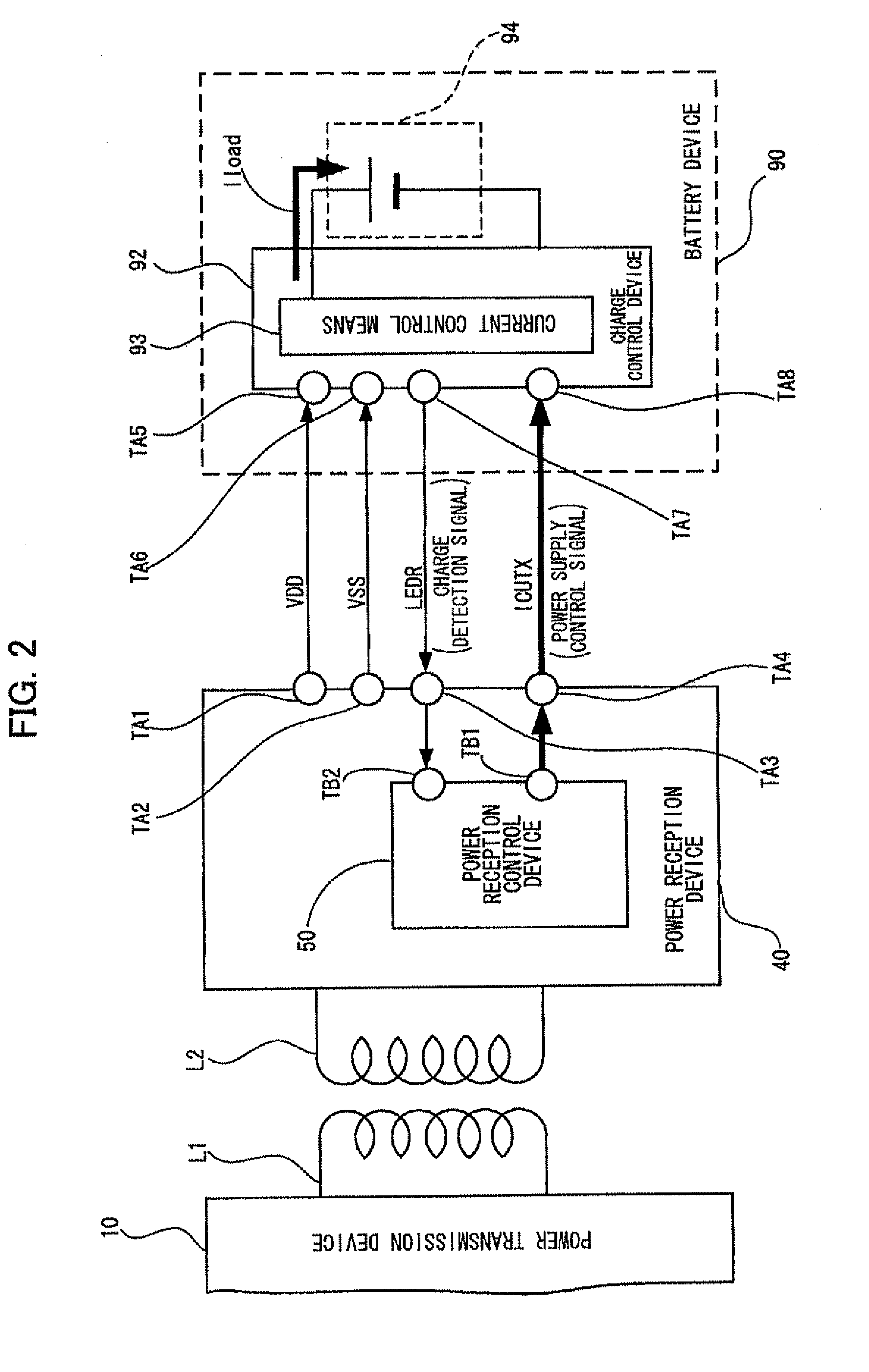
[0142]As shown in FIGS. 1A and 1B, a charger (cradle) 500 (i.e., power-transmission-side electronic instrument) includes a power transmission device (e.g., power transmission module including a power-transmission-side control circuit (power-transmission-side control IC)) 10.

[0143]The charger (cradle) 500 also includes a switch (SW) that causes (triggers) power transmission to start or stop, and a display section (e.g., LED) 16 that is turned ON when the charger transmits power (operates). Note that the...

second embodiment

[0338]This embodiment illustrates a series of sequences of the non-contact power transmission system shown in FIGS. 1 and 3.

[0339]Operation of Non-Contact Power Transmission System

[0340]FIG. 15 is a flowchart showing an outline of an example of the operation of the power transmission device. The operation of the power transmission device 10 is roughly divided into a check on the power transmission target before power transmission (step SA) and a check on the power transmission environment during power transmission (including before power transmission) (step SB) (these steps are enclosed by bold dotted lines).

[0341]The power transmission device 10 starts temporary power transmission when the switch (SW) has been turned ON, as described above (steps S1 and S2).

[0342]The power transmission device 10 then checks whether or not the power-reception-side instrument (510) is placed at an appropriate position (step S3), and performs ID authentication on the power-reception-side instrument 51...


PUM


Abstract

A power reception control device provided in a power reception device of a non-contact power transmission system includes a power-reception-side control circuit that controls an operation of the power reception device, and a power supply control signal output terminal that supplies a power supply control signal to a charge control device, the power supply control signal controlling power supply to a battery. The power-reception-side control circuit controls a timing at which the power supply control signal (ICUTX) is output from the power supply control signal output terminal. The operation of the charge control device is compulsorily controlled using the power supply control signal (ICUTX).

Description

[0001]Japanese Patent Application No. 2007-186109 filed on Jul. 17, 2007, is hereby incorporated by reference in its entirety.BACKGROUND OF THE INVENTION[0002]The present invention relates to a power reception control device, a power reception device, a non-contact power transmission system, a charge control device, a battery device, and an electronic instrument.[0003]In recent years, non-contact power transmission (contactless power transmission) that utilizes electromagnetic induction to enable power transmission without metal-to-metal contact has attracted attention. As application examples of non-contact power transmission, charging a portable telephone, charging a household appliance (e.g., cordless telephone handset or watch), and the like have been proposed.[0004]JP-A-2006-60909 discloses a non-contact power transmission device using a primary coil and a secondary coil, for example. JP-A-2006-166619 discloses the circuit configuration of a charging device for a secondary batt...

Claims


Application Information

Patent Timeline
IPC IPC(8): H02J17/00H02J7/00
CPCH02J7/0011H02J7/025H02J7/00H02J2007/0096H02J5/005H02J7/0052H02J17/00H02J50/10H02J50/60H02J7/00045H02J50/90H02J50/12H02J7/00034H02J50/80H02J7/0069H02J7/007H02J7/0047H04B5/0037
Inventor YODA, KENTAROKAMIJO, TAKAHIROONISHI, KOTAKAMIYAMA, MASAYUKISHIOZAKI, NOBUTAKA
Owner SEIKO EPSON CORP
Why Eureka
Try Eureka