Clamped plate seal

a technology of sealing plate and sealing plate, which is applied in the direction of liquid fuel engines, vessel construction, marine propulsion, etc., can solve the problems of reducing engine or turbine performance, gaps between the sidewalls of the dovetail groove and the sidewalls of the bucket dovetail, and considerable thermal and centrifugal stresses, so as to reduce cooling flow leakage

Active Publication Date: 2009-01-22
GENERAL ELECTRIC CO
View PDF8 Cites 16 Cited by
  • Summary
  • Abstract
  • Description
  • Claims
  • Application Information

AI Technical Summary

Benefits of technology

[0009]A seal for reducing cooling flow leakage in a dovetail joint of a turbomachine is provided, in one aspect of the invention. The turbomachine comprises a rotor wheel and a plurality of buckets. Buckets may also be referred to as blades or airfoils. A rotor wheel has a plurality of rotor dovetail slots, and these slots are circumferentially arranged around the outer perimeter of the rotor wheel. The rotor dovetail slots extend from a forward axial surface of the rotor wheel to an aft axial surface of the rotor wheel. Buckets include bucket dovetails, and the bucket dovetails are arranged to mate with the rotor dovetail slots. A dovetail joint is formed at the interface between the bucket dovetails and the rotor dovetail slots, and...

Problems solved by technology

Since the rotor blades of the turbine are subject to the hottest temperatures of the combustion gases and rotate at high speed they are subject to considerable thermal and centrifugal stresses during operation.
Additionally, gaps can exists between the sidewalls of the dovetail groove and the sides of the bucket dovetail.
These gaps allow cooling air to escape and result in reduced engin...

Method used


Image

  • Clamped plate seal
  • Clamped plate seal
  • Clamped plate seal

Examples


Embodiment Construction

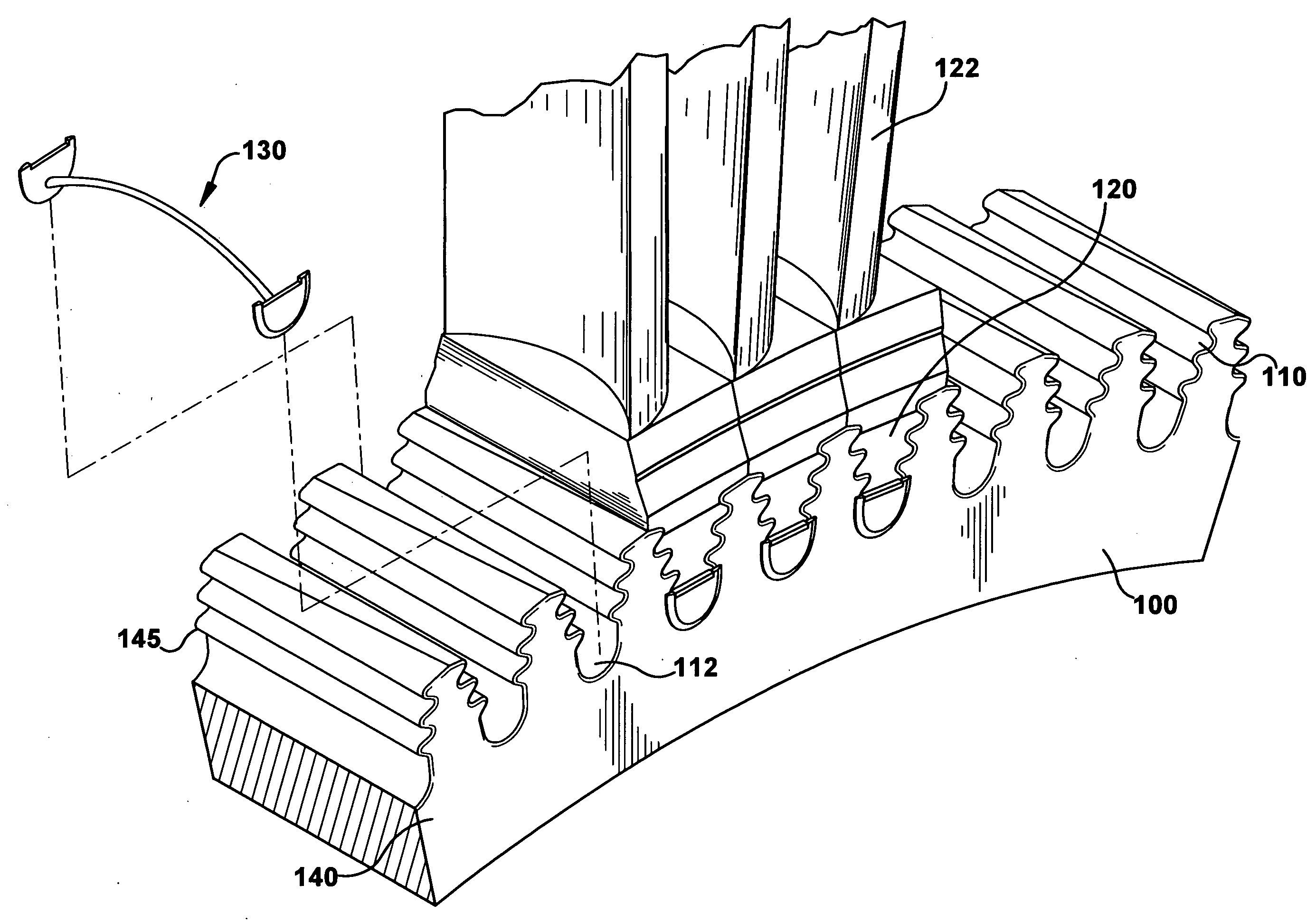
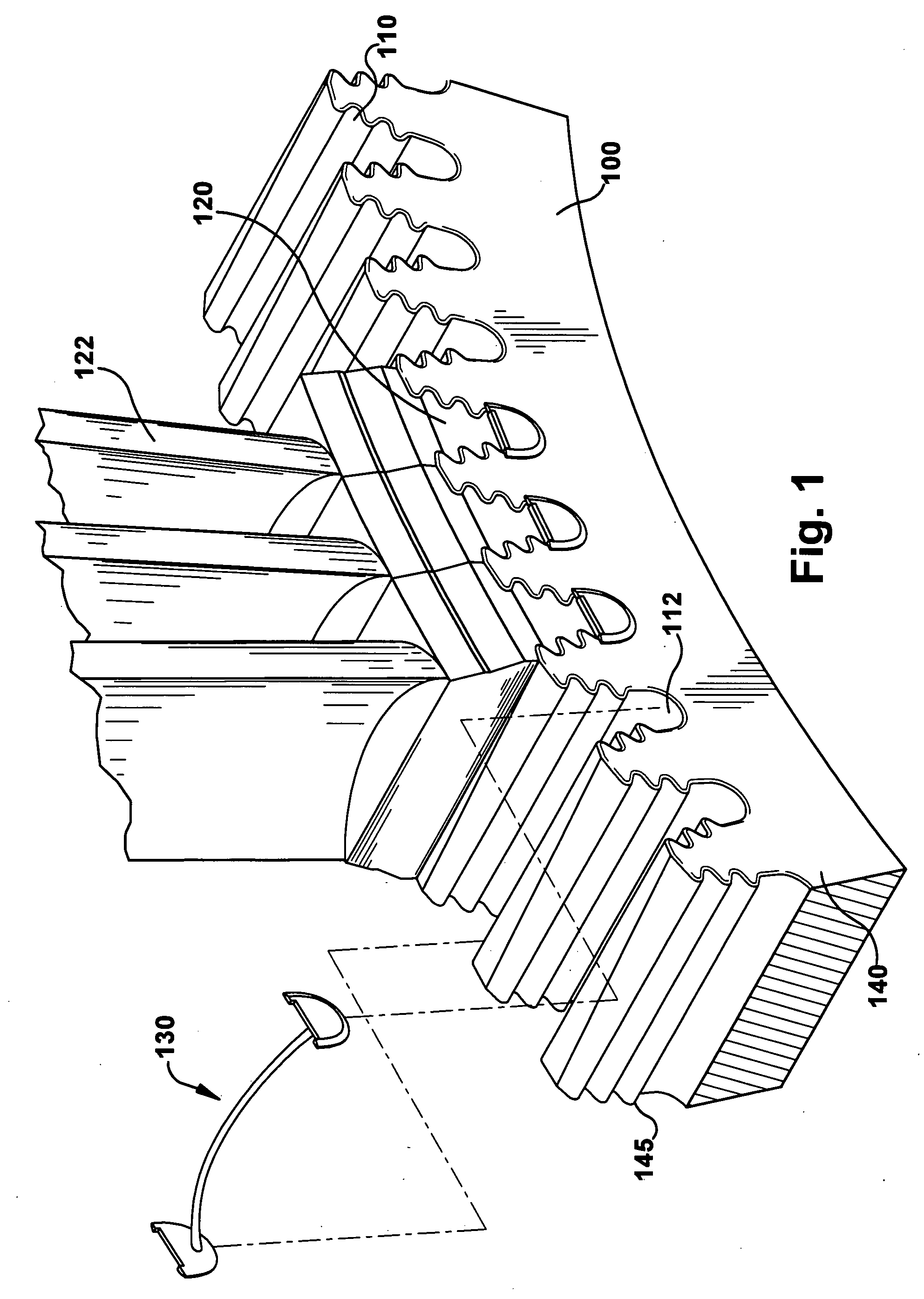
[0017]Referring to FIG. 1, a portion of a turbine rotor wheel 100 having female rotor dovetails 110 is shown. The rotor dovetails 110 may be spaced at even intervals around the entire circumference of the rotor wheel 100. The rotor dovetails 110 extend in a generally axial direction, which may be parallel to the axis of the rotor wheel 100. Rotor dovetails may be of three general types, axial entry, angled entry and curved entry. However, other entry types are within the scope of the invention. Axial entry dovetails, as previously described, have their axis arranged to be generally parallel with the axis of the rotor wheel. Angled entry dovetails have their axis arranged non-parallel or at an angle to the axis of the rotor wheel. Curved entry dovetails have a non-linear and curved axis. Assuming the rotor wheel axis is the X-direction and the radial direction of the rotor wheel is the Y-direction, curved entry dovetails may be curved with respect to one or both of the X and Y direct...


PUM


Abstract

A seal for a dovetail joint in a turbomachine is provided. The seal includes an arcuate member having a first end, a middle portion and a second end. The seal also includes sealing means, which include at least one sealing member. The sealing member can comprise a first sealing member connected to the first end and/or a second sealing member connected to the second end. The dovetail joint is the interface between a bucket dovetail and a rotor dovetail groove, and the seal reduces the amount of cooling flow leakage from the dovetail joint.

Description

BACKGROUND OF THE INVENTION[0001]This application relates to turbomachinery and, in particular, to a sealing device to seal the junction between a dovetail slot and the dovetail base of a blade, bucket, or airfoil in a turbine or compressor.[0002]In turbomachinery, such as a gas turbine, air is pressurized in a compressor and mixed with fuel in a combustor for generating hot combustion gases. Subsequent turbine stages extract energy from the combustion gases for powering the compressor and producing useful work (e.g., rotating the rotor or field of a generator).[0003]A turbine can follow the combustor and may include one or more rows of turbine rotor blades that extract energy from the gases for powering the compressor. The turbine can power an external drive shaft that may be used for powering an electrical generator in a typical industrial gas turbine engine application.[0004]Since the rotor blades of the turbine are subject to the hottest temperatures of the combustion gases and ...

Claims


Application Information

Patent Timeline
IPC IPC(8): B64C11/04
CPCF01D5/3007Y02T50/672F01D11/006Y02T50/60
Inventor LIOTTA, GARY C.WARD, JR., JOHN D.
Owner GENERAL ELECTRIC CO
Why Eureka
Try Eureka