Sliding door and window operating system

a door and window operating system and sliding technology, applied in the direction of wing operation mechanisms, door/window fittings, constructions, etc., can solve the problems of difficult manual opening of windows, large and heavy windows, and generally complicated construction, and achieve simple design, easy and effective opening and closing of doors and windows, and less moving parts.

Inactive Publication Date: 2009-01-29
PETNER ROBERT E
View PDF9 Cites 25 Cited by
  • Summary
  • Abstract
  • Description
  • Claims
  • Application Information

AI Technical Summary

Benefits of technology

[0003]It is an object of the present invention to provide a sliding door and window operating system which easily and effectively opens and closes door and window panels.
[0004]It is another object of the present invention to provide a sliding door and window operating system which is simple in design and uses relatively few moving parts.
[0005]It is a further object of the present invention to provide a sliding door and window operating system which is easily installed and maintained.

Problems solved by technology

Such window panels are usually large and heavy and opening them manually is sometimes difficult.
While there are many prior operating systems, these systems are generally complicated to build and involve the use of too many moving parts, many of which are susceptible of breakage.
Others become an encumbrance in that they are placed on or adjacent to the door or window, and, at the very least, present an unsightly appearance.
Still other operating systems just do not work or work effectively or efficiently.

Method used


Image

  • Sliding door and window operating system
  • Sliding door and window operating system
  • Sliding door and window operating system

Examples


Embodiment Construction

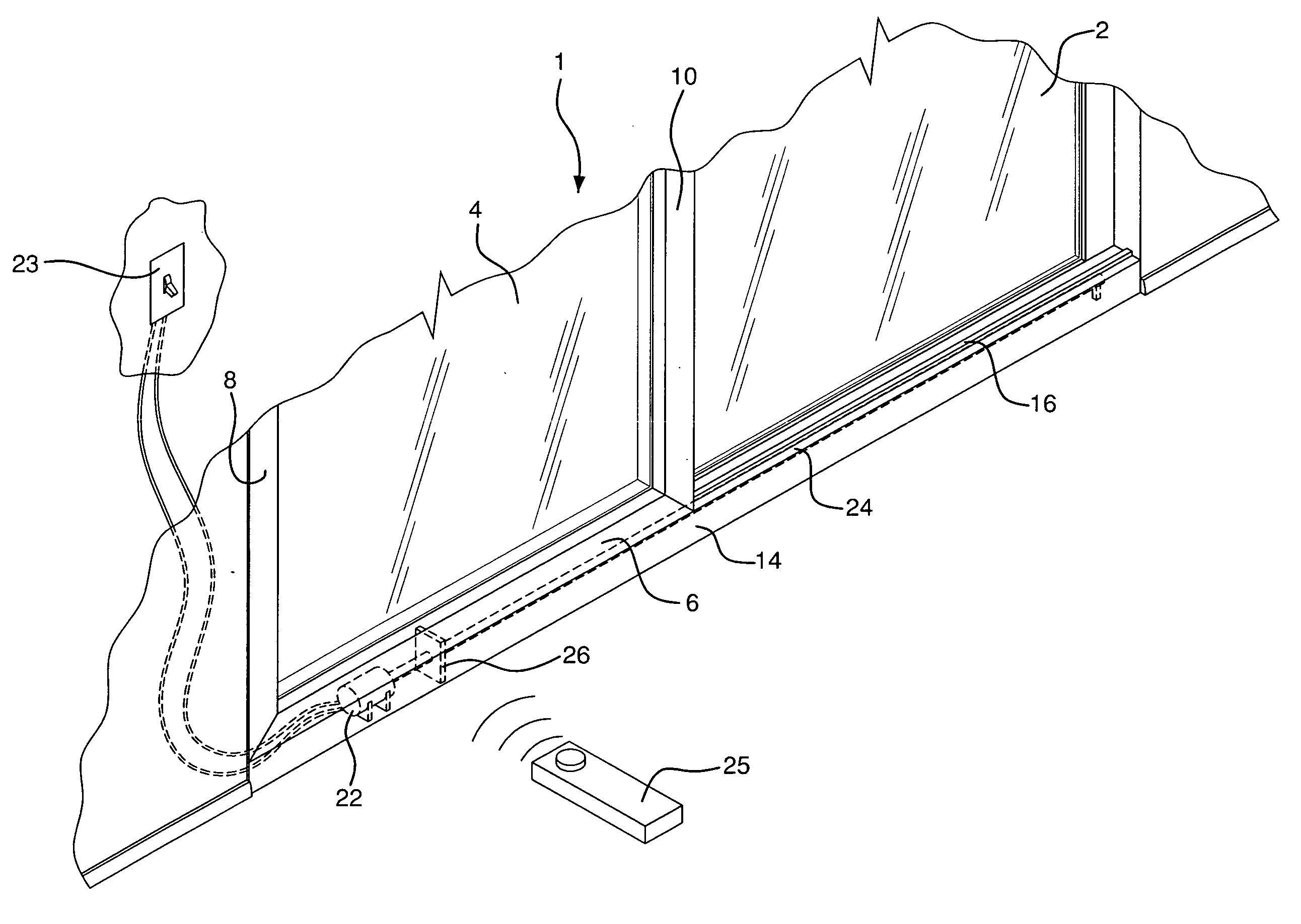
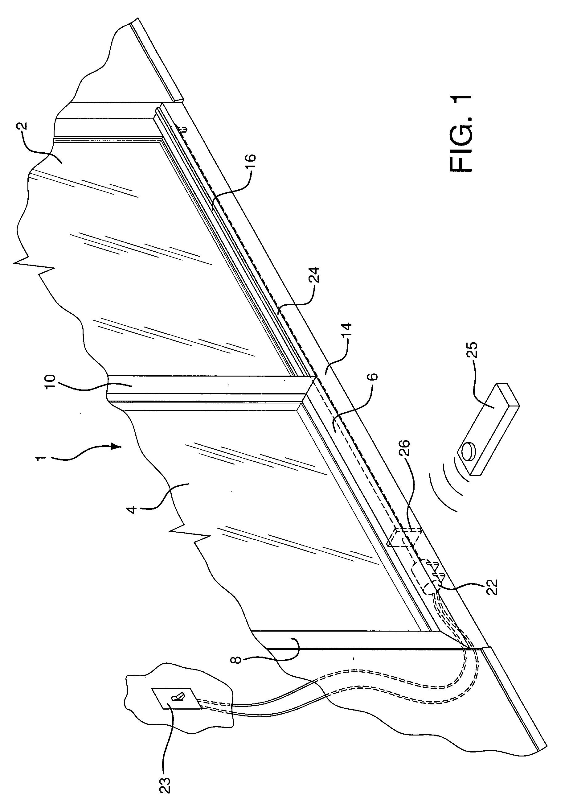
[0014]The panel operating system of the present invention is clearly illustrated in FIGS. 1-5. The lower section of patio sliding door unit 1 is shown in FIG. 1. Door unit 1 comprises fixed transparent door panel 2 and slideable transparent door panel 4. Panel 4 is surrounded by frame members 6, 8, and 10. Frame member 6 extends between frame members 8 and 10 and the full width of panel 4. As best seen in FIG. 4, cut-out opening 12 is inset in frame member 6.

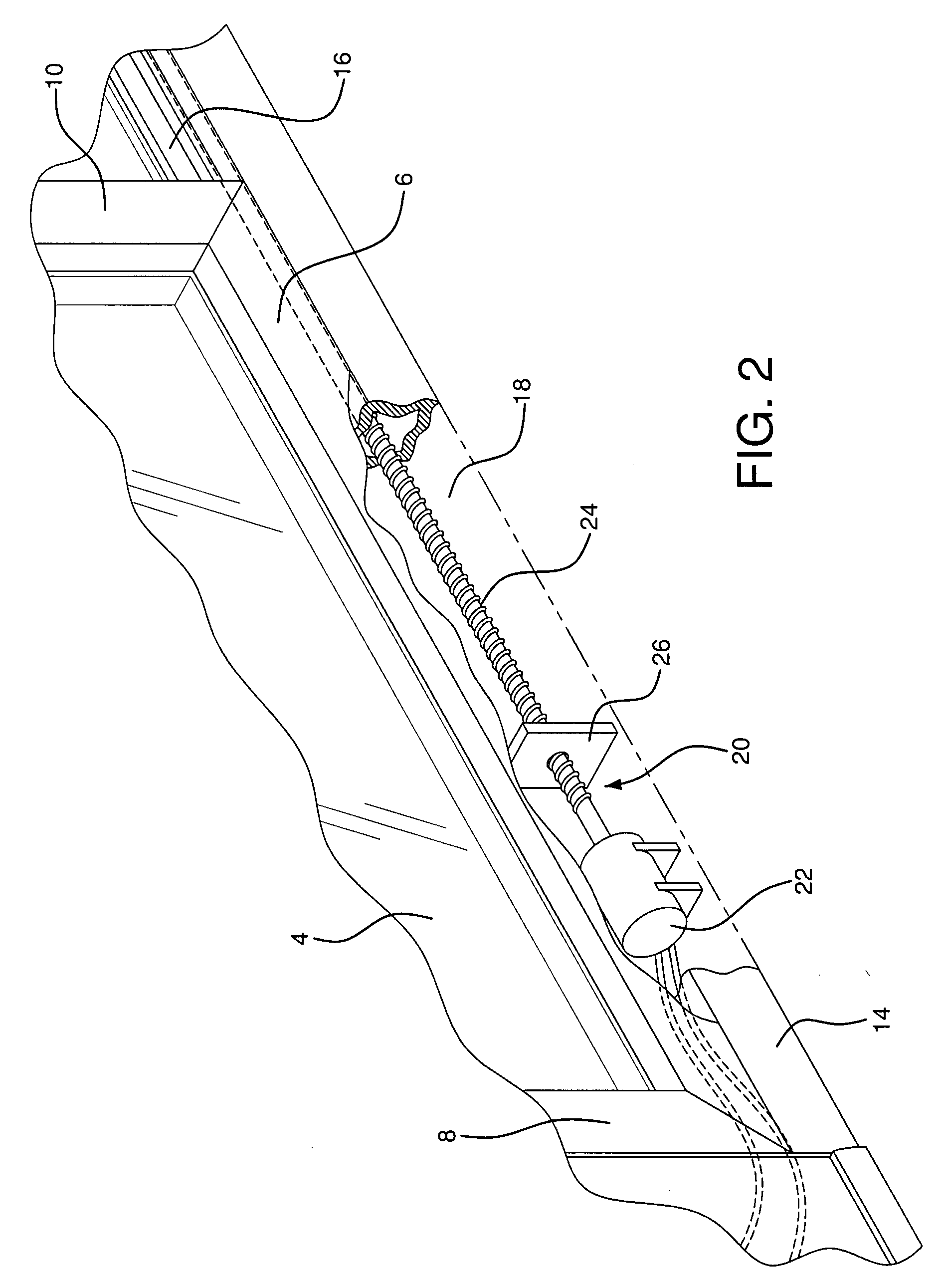
[0015]Frame member 6 is positioned atop casing 14, which extends the full length of door unit 1 and encloses space 18 in which door conveying system 20 is housed. Frame member 6 is configured to slideably move along tracks 16 on casing 14. System 20 comprises electric motor 22, or equivalent power means. Conveying system 20 also comprises lead screw 24 which is connected to motor 22 and extends substantially the full length of casing 14. Guide block 26 is located around and is configured to be driven back and forth lead screw 24...


PUM


Abstract

A novel sliding door and window operating system is especially conducive for use on sliding patio doors and larger window panels. The system uses a small motor to electrically power and rotate a lead screw enclosed within a casing. A guide block on the lead screw is positioned within an opening, inset into the door or window panel which is to be slideably moved. The motor is actuated by use of a switch. The motor rotates the lead screw which in turn moves the guide block back and forth longitudinally within the casing. As the guide block is located within the inset opening of the door or window panel, as the guide block moves it carries the panel along with it, thus opening and closing the panel.

Description

BACKGROUND OF THE INVENTION[0001]The use of sliding doors, windows and similar closures, both in residential and commercial spaces, is well known. Transparent sliding window panels, especially, are used in glass patio doors not only for ingress and egress, but also to allow one to look through a relatively wide, floor to ceiling area. Such window panels are usually large and heavy and opening them manually is sometimes difficult. As a result, automatic sliding door and window opening and closing operating systems, which eliminate the need to struggle with a door or window, have been developed. For example, there are door and window systems which employ belt driven pulleys, others which have complex gear operating systems, and some even use light beams to control door and window panel movement. While there are many prior operating systems, these systems are generally complicated to build and involve the use of too many moving parts, many of which are susceptible of breakage. Others b...

Claims


Application Information

Patent Timeline
Patent Type & Authority Applications(United States)
IPC IPC(8): E05D15/06
CPCE05F15/652E05Y2900/132
Inventor PETNER, ROBERT E.
Owner PETNER ROBERT E
Why Eureka
Try Eureka