Aromatic Drain Device

a technology of aromatic drain and p-trap, which is applied in the direction of sewer cleaning, tobacco, disinfection, etc., can solve the problems of foul odor, odor problems in the p-trap, and odor problems in the room and adjacent areas, so as to mask or eliminate foul odor, simple and easy to change, and prolong the release period

Inactive Publication Date: 2009-01-29
MANGROM MARK A
View PDF70 Cites 12 Cited by
  • Summary
  • Abstract
  • Description
  • Claims
  • Application Information

AI Technical Summary

Benefits of technology

[0013]The present invention is directed to an aromatic drain device attachable to and suspending below a floor drain cover. The device comprises a retaining device that retains an aromatic media that continually releases pleasant fragrances to mask or eliminate foul odors emanating from the floor drain. The device provides for extending release periods and is simple and easy to change without obstructing drain flow.
[0014]It is therefore an object of the present invention to provide a novel aromatic device for masking or eliminating odors emanating from the floor drain.
[0015]It is an object of the present invention to provide an aromatic device easily securable to a floor drain.
[0017]It is an object of the present invention to provide an aromatic device that provides continual aromatic action for an extending duration.
[0018]It is an object of the present invention to provide an aromatic drain device providing quick, easy replacement of aromatic media.
[0021]In a second aspect, the device comprises a retaining device that may be easily and quickly removed from the floor drain facilitating quick replacement of aromatic media, wherein the retaining device holds either solid, gel based, or liquid based aromatic media.

Problems solved by technology

Many public facilities having floor drains suffer from odor problems emanating from the floor drain.
This problem is especially prevalent in public restrooms.
The water in the p-trap quickly becomes dirty and emanates foul odor into the room and adjacent areas.
Additionally, the sanitizing liquid does not provide continuous aroma to the room.
These systems also do not provide a continuous release of aroma into the room.
While these devices mask foul odors immediately following discharge, the active aromatic agents quickly disperse into the room, failing to effectively mask or eliminate the odors.
Most of these devices require special drain modifications to hold the device, increasing expense to the owner and making them impractical for contractor installation.
These devices may also have the tendency to aggravate drain problems by catching dirty water around the device.

Method used


Image

  • Aromatic Drain Device
  • Aromatic Drain Device
  • Aromatic Drain Device

Examples


Embodiment Construction

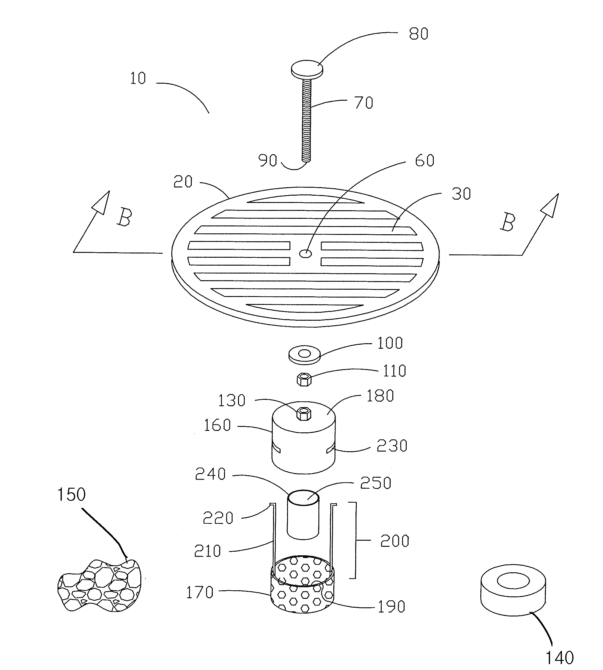
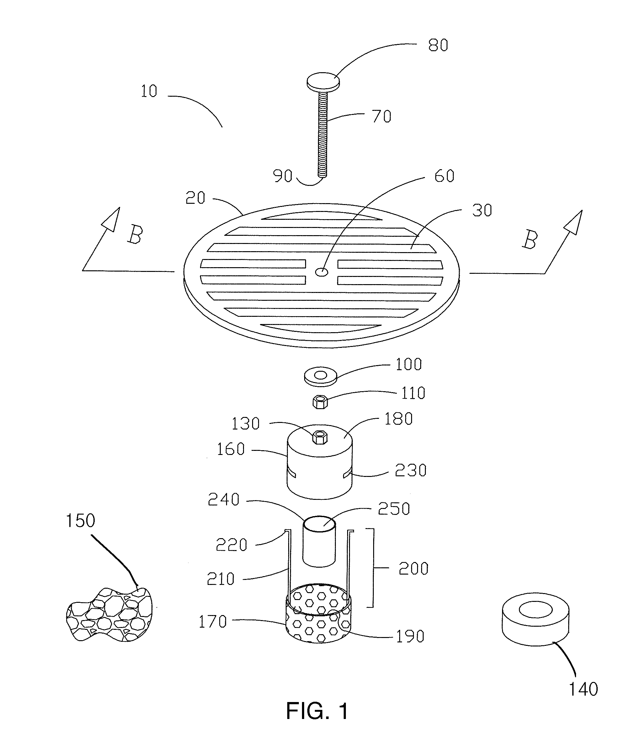
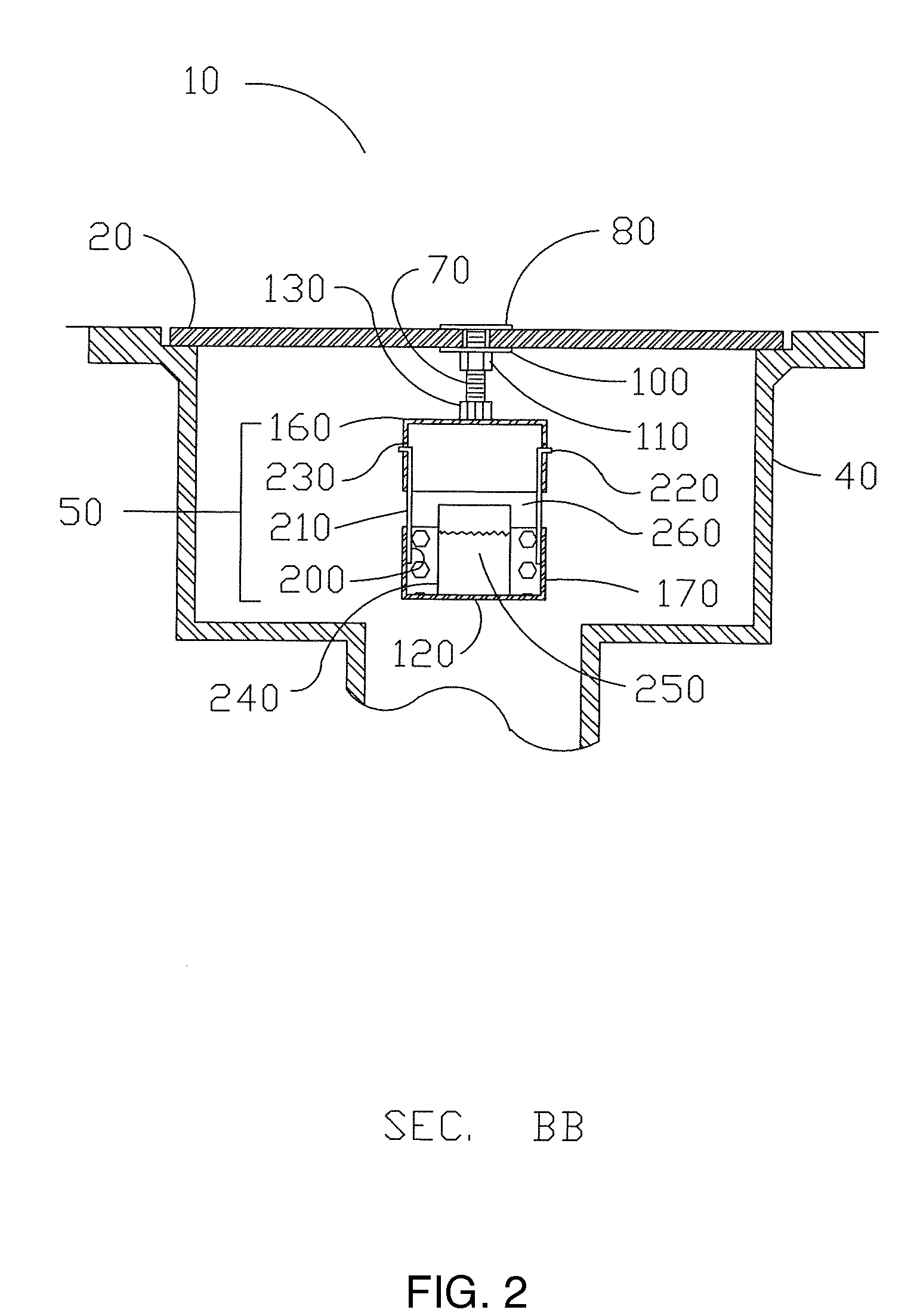
[0027]Referring now to the drawings in greater detail, FIG. 1 and FIG. 2, an aromatic floor drain device 10 is shown. A floor drain cover 20 has a plurality of drain openings 30 formed therein. The drain openings 30 allow water and debris washed from the floor to pass through the openings and into the floor drain 40. The drain cover 20 removably secures to a floor drain 40. A retaining device 50 defining a volume therein releasably secures to the drain cover 20. In the illustrated embodiment, the drain cover 20 has a bolt opening 60 centrally formed therein. The bolt opening 60 is adapted to receive an elongated threaded bolt 70 having a flat head 80 and a free end 90. The bolt opening 60 receives the threaded bolt 70 so that the flat head 80 is essentially flush with the top of the drain cover 20 while the free end 90 extends below the drain cover 20 and into the cavity defined by the floor drain 40. The bolt opening 60 may be countersunk to allow the flat head 80 to recess into th...


PUM

PropertyMeasurementUnit
volumeaaaaaaaaaa
aromaticaaaaaaaaaa
areasaaaaaaaaaa

Abstract

An aromatic drain device comprising a perforate retaining device defining a volume for retaining an aromatic media therein, the retaining device releasably secured to a removable drain cover and positioned to extend below the drain cover into the cavity defined by the floor drain wall.

Description

CROSS-REFERENCE TO RELATED APPLICATIONS[0001]This application is a DIVISIONAL of prior non-provisional application No. 11 / 382,541, filed May 10, 2006, which is hereby incorporated by reference in its entirety.STATEMENT REGARDING FEDERALLY SPONSORED RESEARCH OR DEVELOPMENT[0002]Not Applicable.[0003]Attorney Docket No: 08-267[0004]Parent Application Art Unit: 1797BACKGROUND OF THE INVENTION[0005]This is a DIVISIONAL of application Ser. No. 11 / 382,541, filed May 10, 2006, publication number US 2007-0262006 A1, which is hereby incorporated by reference in its entirety.[0006]1. Field of Invention[0007]This invention relates generally to a device positioned inside a floor drain for deodorizing public facilities and the like.[0008]2. Description of the Prior Art[0009]Many public facilities having floor drains suffer from odor problems emanating from the floor drain. This problem is especially prevalent in public restrooms. As facilities are cleaned, dirt, grime, and bacteria collect in the...

Claims


Application Information

Patent Timeline
Patent Type & Authority Applications(United States)
IPC IPC(8): A61L9/00
CPCE03C1/126E03F2005/0416E03F5/041E03F5/0407
Inventor WORTH, THOMAS W.
Owner MANGROM MARK A
Why Eureka
Try Eureka