
Frame assembly for in-line skate

Inactive Publication Date: 2009-01-29
SUNSHINE DISTRIBUTION
View PDF33 Cites 2 Cited by
  • Summary
  • Abstract
  • Description
  • Claims
  • Application Information

AI Technical Summary

Benefits of technology

[0010]In one embodiment, the wheel axle openings are located adjacent a front and rear end, respectively, of the frame, and a second pair of aligned wheel axle openings are provided in the H-block insert on opposite sides of the grinding surface for rotatably receiving a second pair of in-line skate wheels. In an alternative embodiment, only front and rear in-line skate wheels are mounted in the frame, and the grinding surface extends over an extended region between the front and rear wheels to provide for a greater range of grinding and sliding maneuvers.
[0013]In one embodiment, the H-block insert has a central, downwardly facing arcuate grinding surface, and third and fourth wheels are secured between the spaced side walls of the H-block insert, the third wheel being located in a space between the grinding surface and the front wheel, and the fourth wheel being located in a space between the grinding surface and rear wheel. In another embodiment, the skate has only a front wheel and a rear wheel, and the H-block insert extends along a major portion of the length of the frame and has a first end adjacent the front wheel and a second end adjacent the rear wheel, with an elongate grinding surface extending along a major portion of the length of the H-block insert and terminating short of the first and second ends of the insert. The grinding surface in this case may be generally V-shaped in longitudinal cross-section, with an apex and end portions which taper downwardly from the apex towards the opposite ends of the grinding surface. This alternative allows for more freestyle, acrobatic maneuvers using the extended grinding surface.

Problems solved by technology

This results in wear and eventually requires replacement of the entire frame.
One problem with some existing H-block insert designs is that the structure of the frame may be weakened by the cut-out or recess which is provided to accommodate mounting of the H-block insert and attachment of the insert to the frame.
This cut-out makes the frame less stiff, so that it is more likely to bend and eventually crack.
The pressure on the outside wheels on landing after a jump bends the frame and may eventually cause the frame to crack.

Method used


Image

  • Frame assembly for in-line skate
  • Frame assembly for in-line skate
  • Frame assembly for in-line skate

Examples


Embodiment Construction

[0037]Certain embodiments as disclosed herein provide for a frame assembly for an in-line skate which includes a removable H-block insert to provide a sliding or grinding surface.

[0038]After reading this description it will become apparent to one skilled in the art how to implement the invention in various alternative embodiments and alternative applications. However, although various embodiments of the present invention are described herein, it is understood that these embodiments are presented by way of example only, and not limitation. As such, this detailed description of various alternative embodiments should not be construed to limit the scope or breadth of the present invention as set forth in the appended claims.

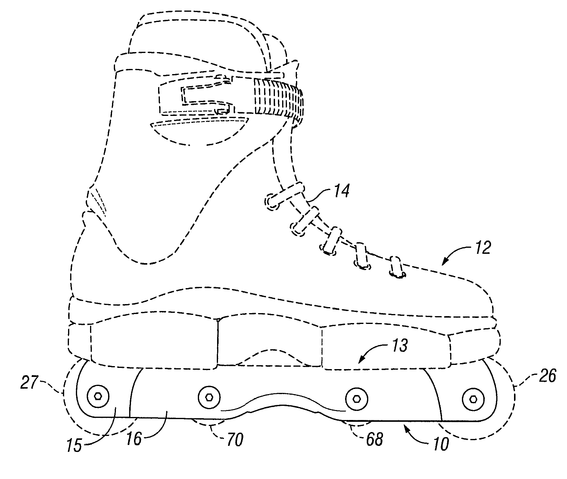
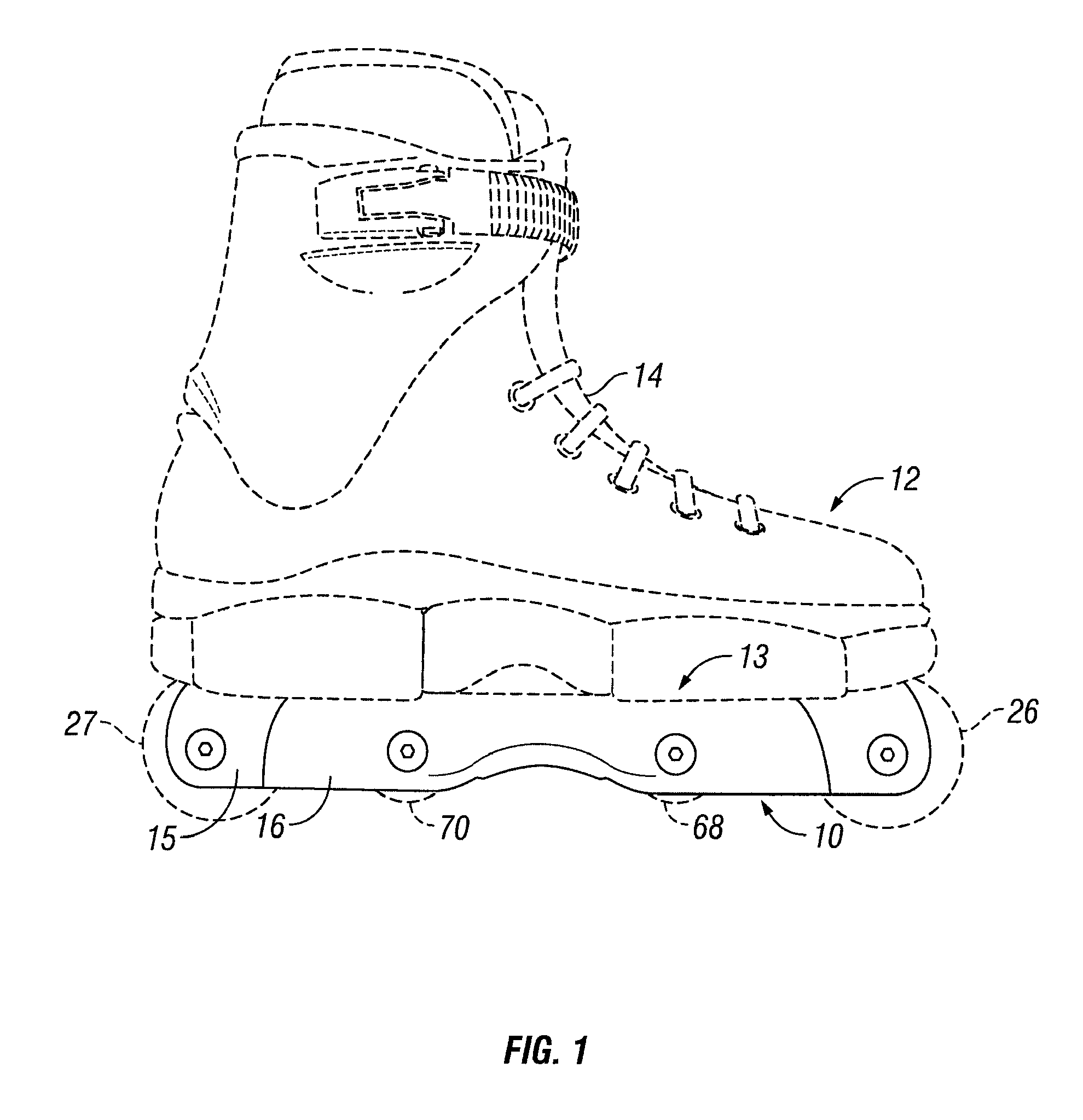
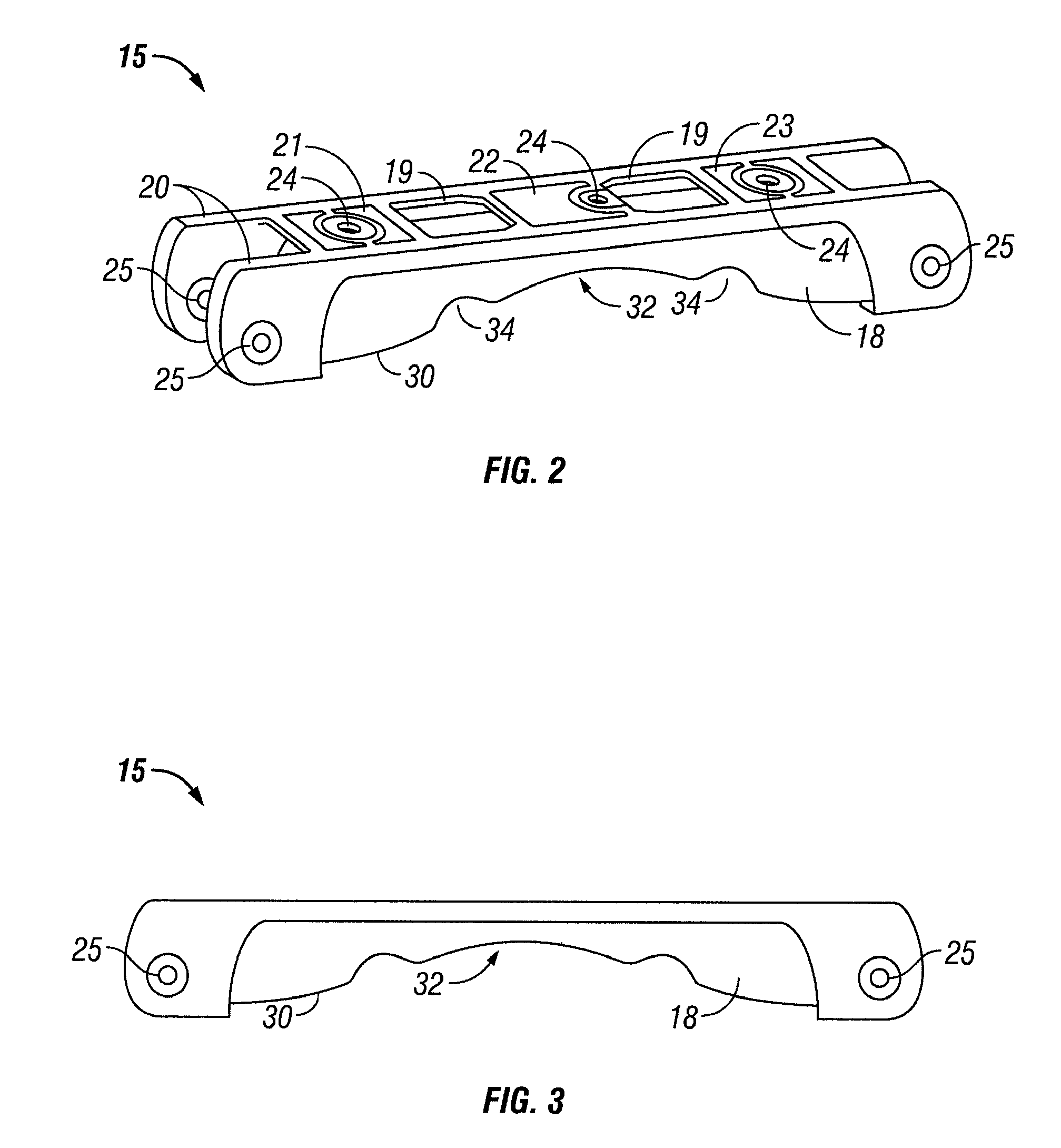
[0039]FIGS. 1 to 14 illustrate a first embodiment of a frame assembly 10 for an inline skate 12. FIG. 1 illustrates the frame assembly 10 attached to the sole 13 of an in-line skate boot 14, while FIGS. 2 to 12 illustrate the separate components of the frame assembly...


PUM


Abstract

An in-line skate frame assembly has a rigid frame and an elongate grinding insert releasably engaged with the frame. The frame and insert are secured together to the sole of a shoe or boot by frame bolts extending through upper portions of the frame and insert. The frame has spaced side walls with downwardly facing recessed regions in which the insert is mounted. The insert extends along a major portion of the length of the frame and has a downwardly facing, centrally located grinding surface which terminates short of the opposite ends of the insert. Different inserts with grinding surfaces of different shapes and lengths are releasably secured to the frame for performing alternative grinding maneuvers.

Description

BACKGROUND[0001]1. Field of the Invention[0002]The present invention relates generally in-line skates and is particularly concerned with an in-line skate frame with a H-block or grinding insert.[0003]2. Related Art[0004]In-line skates typically have a series of wheels arranged one after the other in a single row or line in the running direction. The wheels are rotatably mounted on a frame, and the frame is connected to the sole of a shoe or skate boot, or may be integrated into the sole of the boot. The frame typically has a pair of side plates between which the wheels are mounted, and an upper portion with openings through which a frame bolt extends to attach the frame to the sole of a boot.[0005]In some skates, particularly so-called extreme, aggressive, or stunt skates, the center of the lower edge of each plate is arched to provide a sliding surface for the skater to slide or grind along a railing, curbstone edge, or the like. This results in wear and eventually requires replace...

Claims


Application Information

Patent Timeline
IPC IPC(8): A63C17/06A43B5/16
CPCA63C2201/02A63C17/06
Inventor WEGENER, ANDREAS C.
Owner SUNSHINE DISTRIBUTION
Learn More