Directional radio signal detection apparatus using a sense and loop antennas

Inactive Publication Date: 2014-02-20
NGUYEN SON
View PDF4 Cites 4 Cited by
  • Summary
  • Abstract
  • Description
  • Claims
  • Application Information

AI Technical Summary

Benefits of technology

[0013]The use of multiple loop antennas allows for the creation of field patterns not possible with a single loop antenna, due to the fact that multiple loop antennas increase the degrees of freedom. The available parameters include loop antenna size, spacing and location, and loop antenna angle relative to the other antennas.
[0014]When compared to phase based systems utilizing loop antennas, a system utilizing the invention described herein may have significantly better range. The overall sensitivity of the phase based system is dependent on all the antennas. Thus a phase based system's sensitivity is only as good as the least sensitive antenna Small and medium loop antennas often used in phase based systems do not have the same sensitivity as the typical sense antennas used in these systems. The apparatus described herein obtains the directional signal from the sense antenna.
[0015]In certain phased based implementation where two loop antennas and a sense antenna are used, and the antennas are properly configured, the signal strength method described herein may be u

Problems solved by technology

The use of multiple loop antennas allows for the creation of field patterns not possible with a

Method used


Image

  • Directional radio signal detection apparatus using a sense and loop antennas
  • Directional radio signal detection apparatus using a sense and loop antennas
  • Directional radio signal detection apparatus using a sense and loop antennas

Examples


Embodiment Construction

[0027]The present disclosure consists of a non-directional antenna such as a dipole, helical or monopole antenna referred as the sense antenna and two or more loop antennas. Using the loop antennas to absorb the energy, a non-ambiguous antenna response on the sense antenna can be created.

[0028]A dipole, monopole or helical antenna oriented in the z direction has a gain pattern which is uniform in the x and y axis. Thus a signal coming from any direction in the x-y plane will result in the same signal level. A loop antenna is directional and has symmetrical gain pattern.

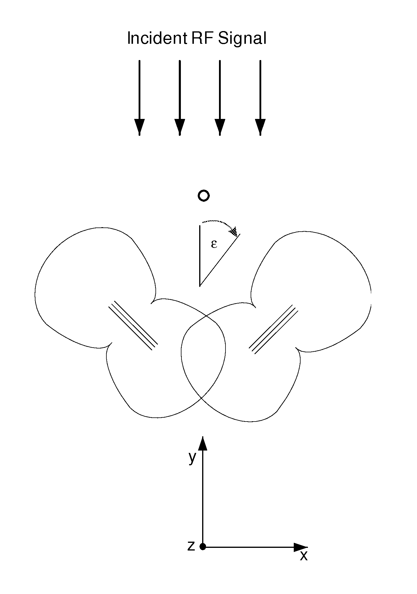
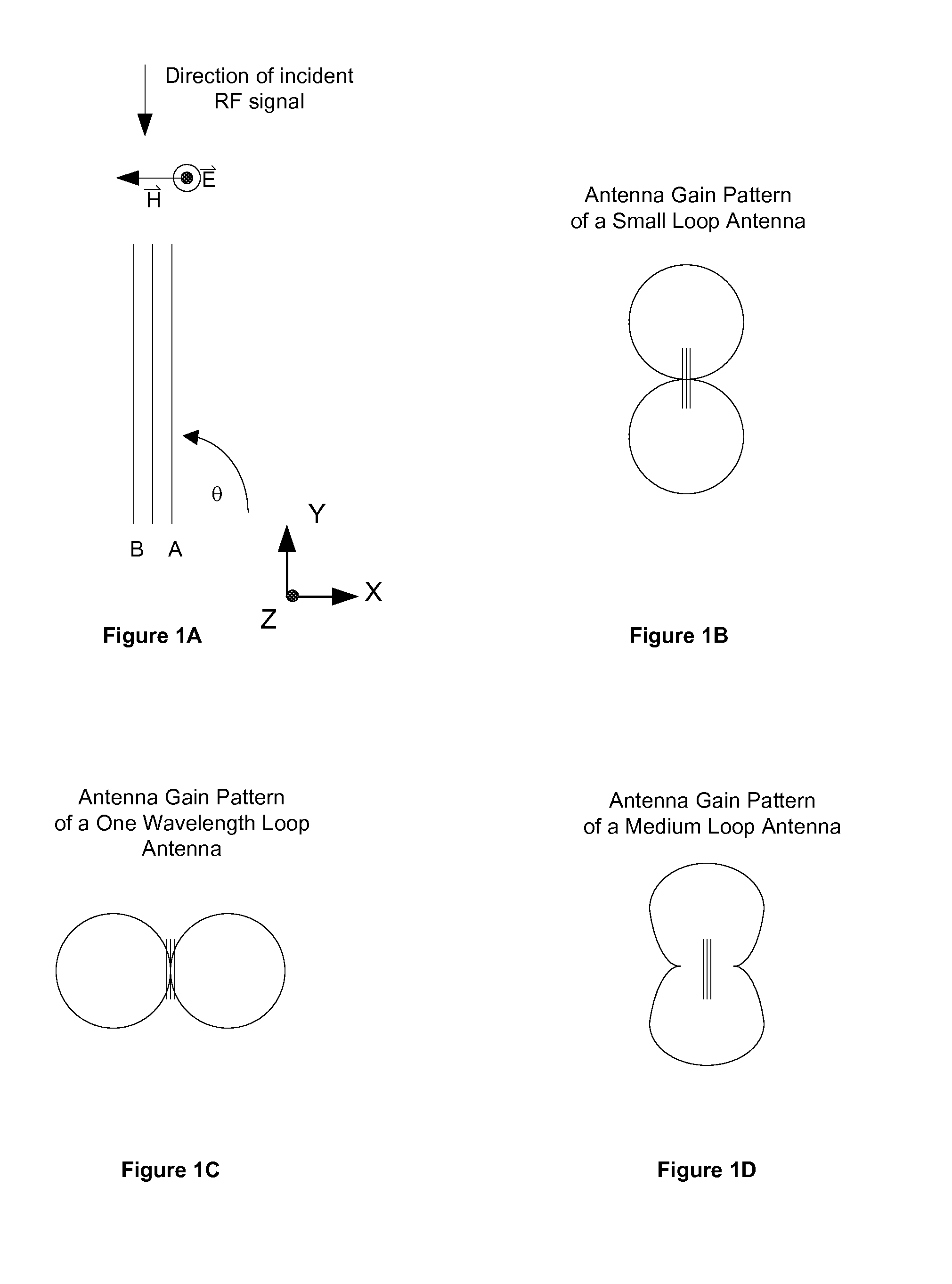
[0029]FIG. 1A shows a loop antenna wound in the Y and Z plane with Theta (θ), the angle of the loop antenna relative to the incident RF. The bean pattern of a small loop antenna is shown in FIG. 1B and can be characterized by the equations:

0°t)

180°t)

[0030]FIG. 1C shows the beam pattern of a one wavelength antenna and its response can be characterized by the equation:

|cosθ|cos(ωt)

Note that the beam pattern of a small v...


PUM


Abstract

An apparatus for direction finding a received radio signal is enclosed. The receiving apparatus selectively receives on a predetermined frequency to match the transmitter frequency. The receiving apparatus is comprised of one non directional antenna and two or more loop antennas. The loop antennas modify the field of the incident radio signal by absorbing the incident radio frequency energy to create a non-ambiguous gain pattern on the sense antenna that can be used to determine the direction of the incident RF signal.

Description

DESCRIPTION OF PRIOR ART[0001]Directional radio signal detectors are used to find the direction of a radio emitting source such as a radio beacon. These directional detectors can be composed of a single antenna or multiple antennas. Direction of the signal source can be determined using phase technique, signal strength, or a combination of signal strength and phase.[0002]In a phase measurement technique more than one antenna is used. The typical method is to spatially separate the multiple antennas and to measure the difference in time of arrival or equivalently, the phase difference of the signal between the antennas. Other methods utilize a change in the phase of the signal on an antenna depending on the direction of the signal source. These other phase based systems have circuits that sum, difference and / or multiply the antenna signals. The phase information between the antennas is then used to determine the direction of the signal source. Phase based systems typically automatica...

Claims


Application Information

Patent Timeline
IPC IPC(8): G01S3/02
CPCG01S3/06
Inventor NGUYEN, SON
Owner NGUYEN SON
Why Eureka
Try Eureka