Input display apparatus and input display panel

Inactive Publication Date: 2009-01-29
FUJITSU TOSHIBA MOBILE COMM LTD
View PDF1 Cites 55 Cited by
  • Summary
  • Abstract
  • Description
  • Claims
  • Application Information

AI Technical Summary

Benefits of technology

[0009]The present invention has been accomplished to solve the above-described problems. The object of the present invention is to provide an input display apparatus and in

Problems solved by technology

However, this optical system has a problem that stable detection cannot be executed if the degree of illumination of the environment light is low or images are dark.
In addition, complicated control to adjust the detection accuracy in accordance with ambient brightnes

Method used


Image

  • Input display apparatus and input display panel
  • Input display apparatus and input display panel
  • Input display apparatus and input display panel

Examples


Example

[0018]An embodiment of the present invention will be described below with reference to the accompanying drawings.

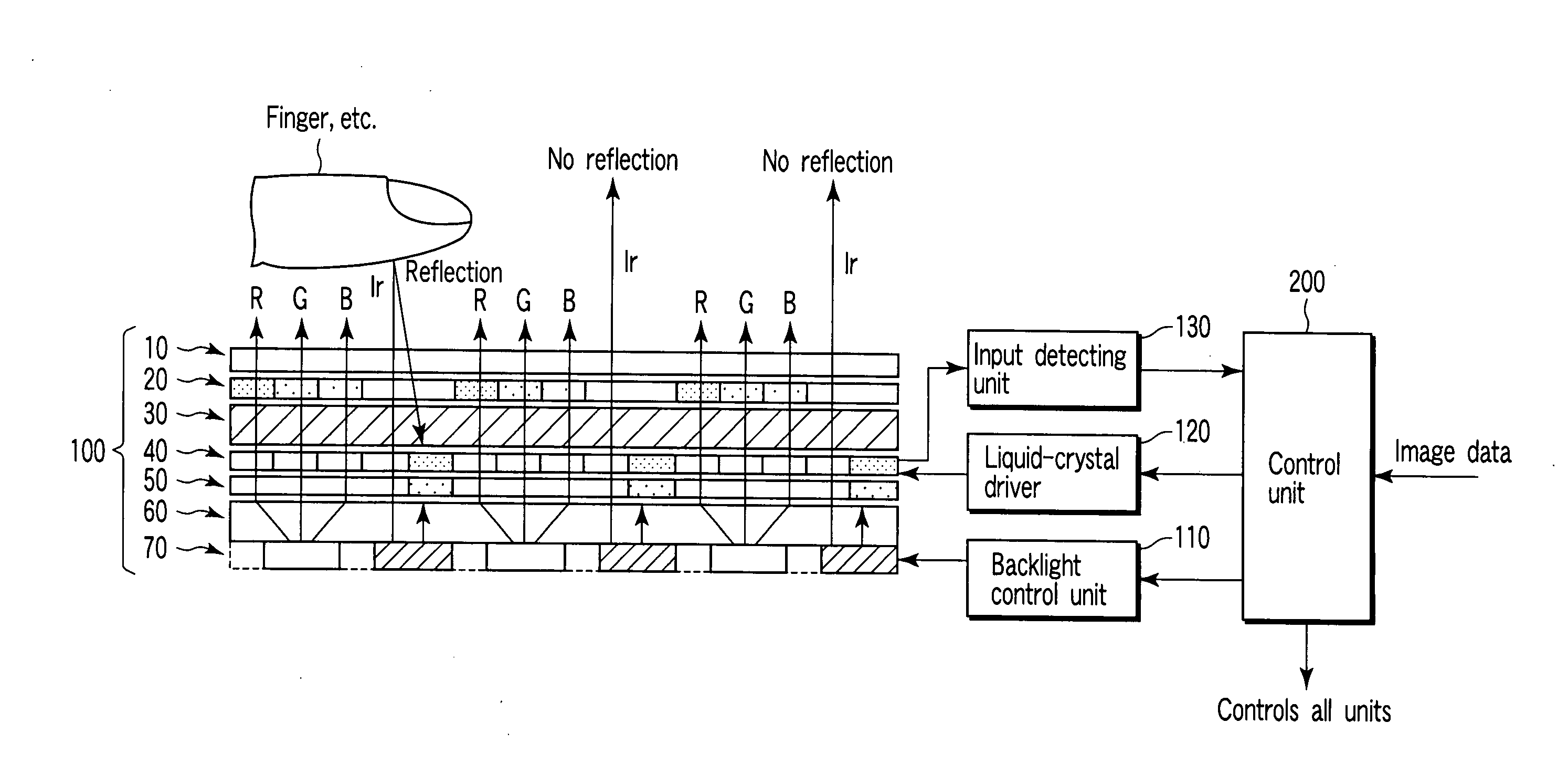
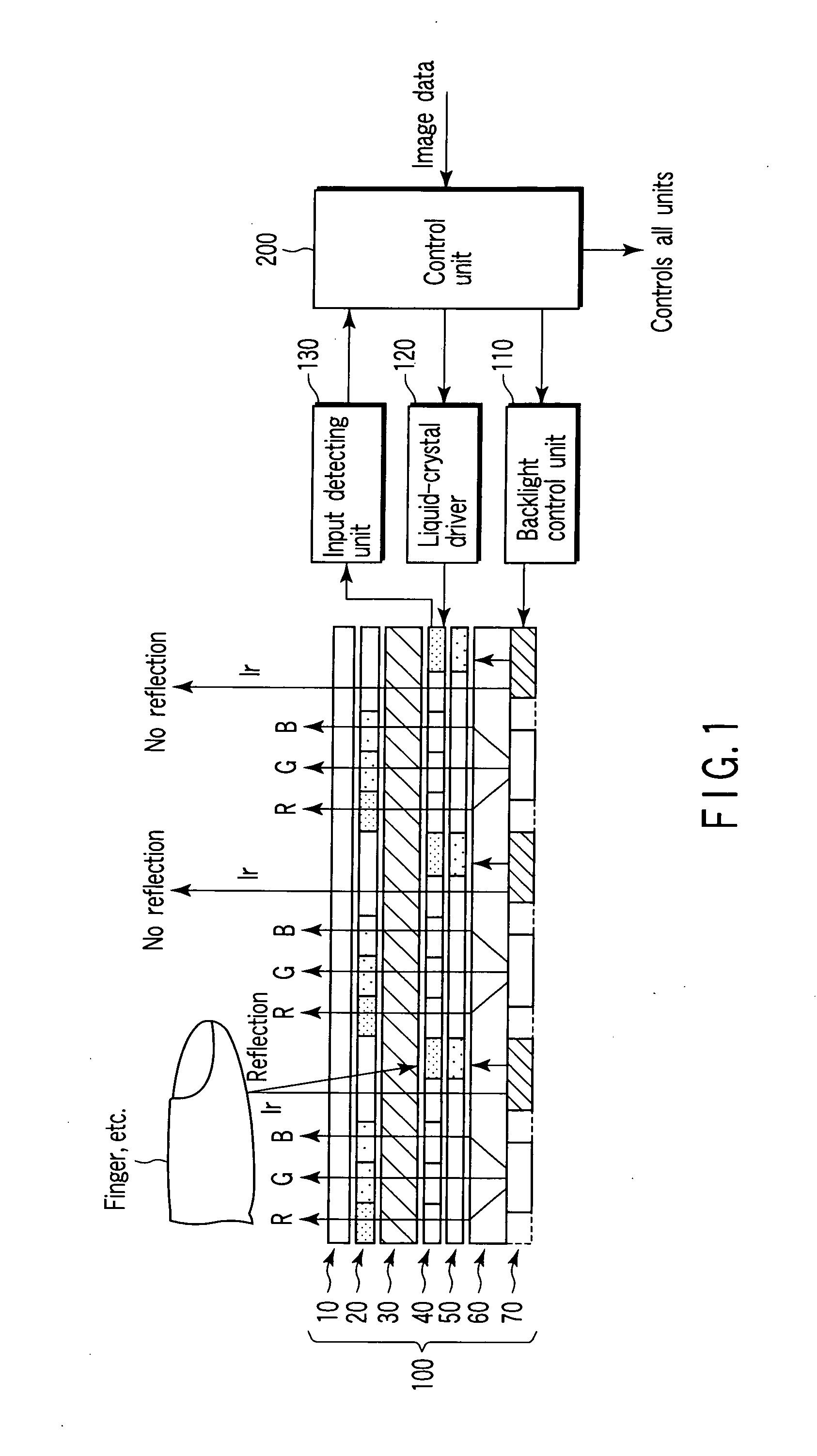
[0019]FIG. 1 shows a structure of an input display apparatus according to an embodiment of the present invention. The input display apparatus comprises an input display panel 100, a backlight control unit 110, a liquid-crystal driver 120, an input detection unit 130 and a control unit 200.

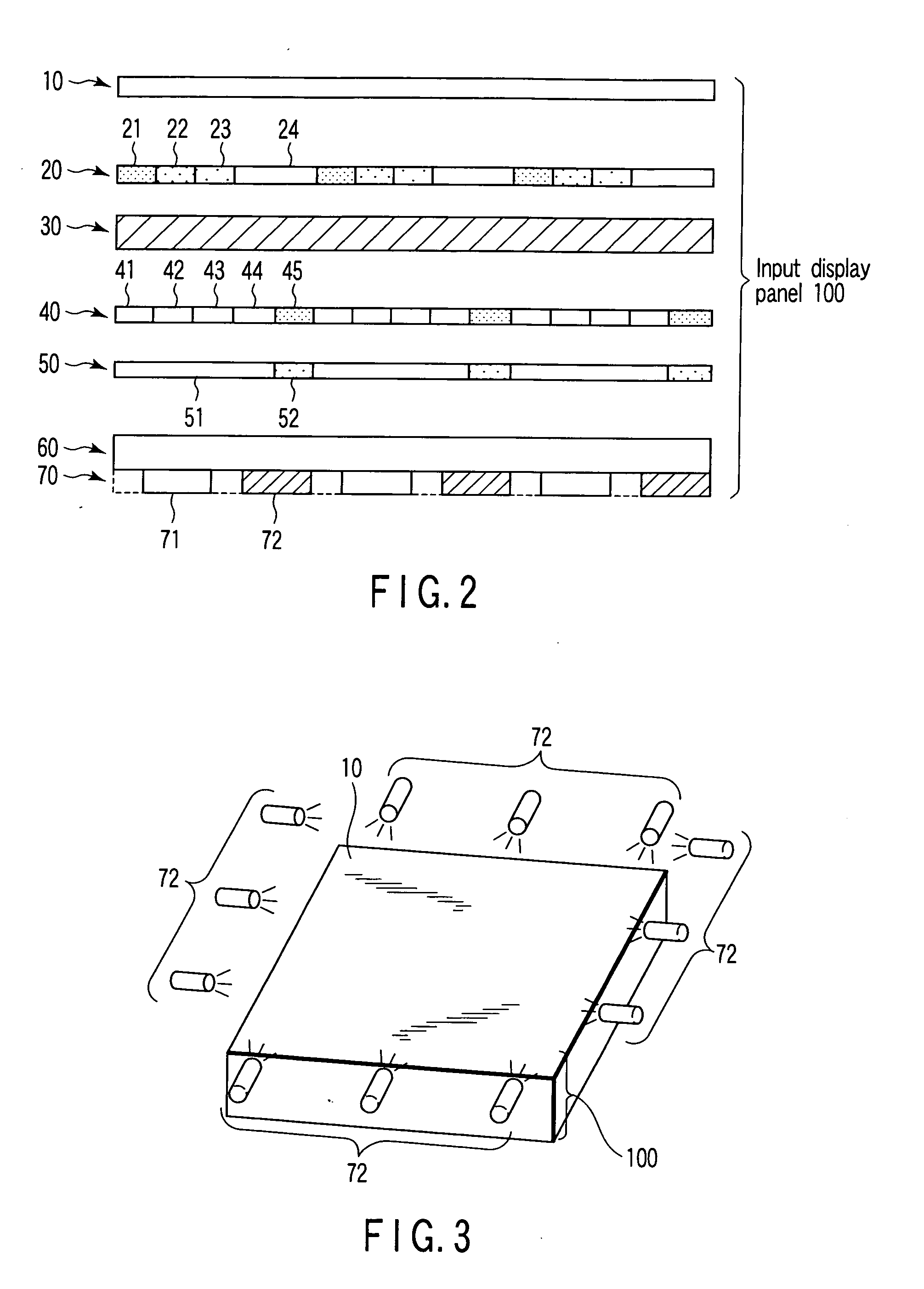
[0020]The input display panel 100 has a multilayered structure as shown in FIG. 2, and comprises a protective layer 10, a filter layer 20, a liquid-crystal layer 30, a TFT (Thin Film Transistor) layer 40, a substrate layer 50, a light guiding plate layer 60 and a backlight layer 70.

[0021]The protective layer 10 is configured to protect the input display panel 100 from an outer pressure and is formed of a transparent and hard resin material such as acryl or the like. The protective layer 10 plays roles of polarization, prevention of reflection and the like besides the protection.

[0022]In ...


PUM


Abstract

Besides a white LED employed as a general backlight, an Ir-LED is provided to apply an infrared light beam from a display face of an input display panel to the outside, reflected light of the infrared light beam is detected by a sensor, and a user's request is thereby accepted.

Description

CROSS-REFERENCE TO RELATED APPLICATIONS[0001]This application is based upon and claims the benefit of priority from prior Japanese Patent Application No. 2007-194828, filed Jul. 26, 2007, the entire contents of which are incorporated herein by reference.BACKGROUND OF THE INVENTION[0002]1. Field of the Invention[0003]The present invention relates to an input display apparatus having an input device and a display device unified therein.[0004]2. Description of the Related Art[0005]A display device comprising an inputting function detects an input in a resistance film system or a capacitance system. Recently, the circuitry has been miniaturized and an optical system of aligning light sensors on a glass substrate of the display device and detecting the input by the light sensors has been developed (cf., for example, Jpn. Pat. Appln. KOKAI Publication No. 2006-238053).[0006]In the optical system, a shadow of a finger formed on the display device is detected by a light sensor, or a light b...

Claims


Application Information

Patent Timeline
IPC IPC(8): G06F3/042
CPCG06F3/0421
Inventor HOSONO, MASAFUMI
Owner FUJITSU TOSHIBA MOBILE COMM LTD
Why Eureka
Try Eureka