Solenoid valve with cylindrical valve guide for the spherical valve element at the pressure inlet

a valve element and valve guide technology, applied in the direction of valve details, valve arrangements, thin material handling, etc., can solve the problems of accelerating the abrasion of not only the valve element and the valve seat, and achieve the effect of stably performing the opening and closing operation

Inactive Publication Date: 2007-01-23
KEIHIN CORP
View PDF13 Cites 17 Cited by
  • Summary
  • Abstract
  • Description
  • Claims
  • Application Information

AI Technical Summary

Benefits of technology

[0006]The present invention has been achieved in view of such situation, and has an object to provide a valve device which can stably perform opening and closing operation of a valve element without lateral oscillation while securing a passage between an inlet port and a valve seat.

Problems solved by technology

Hence, this is a cause of accelerating the abrasion of not only the valve element and the valve seat, but also a push rod which makes the valve element open.

Method used


Image

  • Solenoid valve with cylindrical valve guide for the spherical valve element at the pressure inlet
  • Solenoid valve with cylindrical valve guide for the spherical valve element at the pressure inlet
  • Solenoid valve with cylindrical valve guide for the spherical valve element at the pressure inlet

Examples


Embodiment Construction

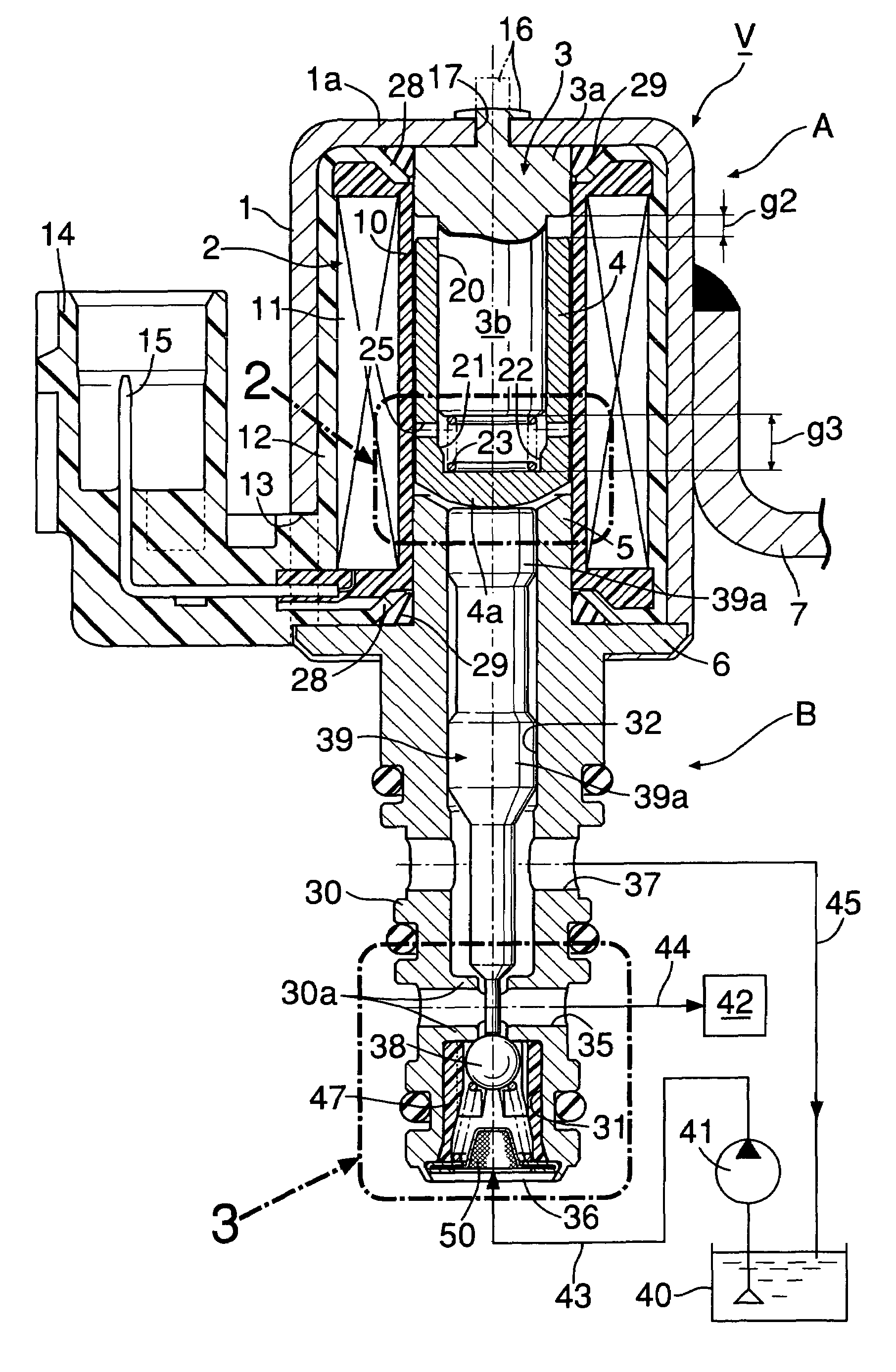
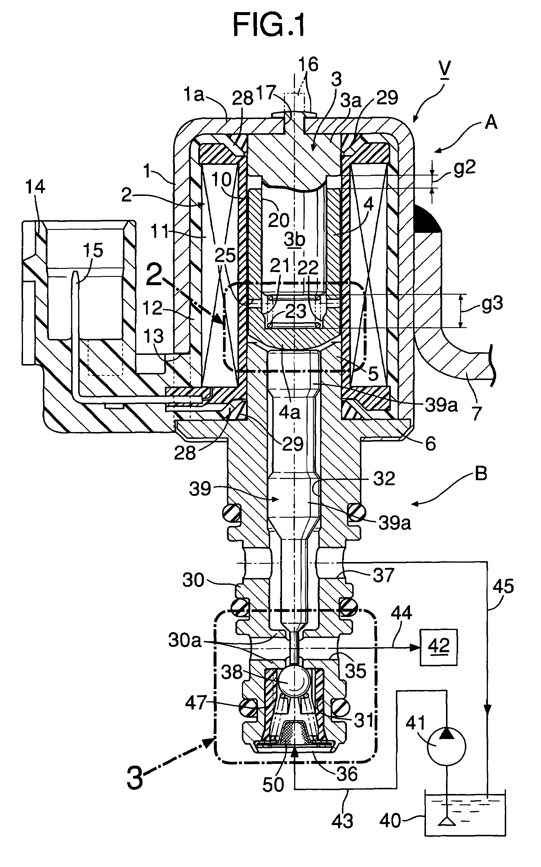
[0037]Referring first to FIG. 1, a solenoid valve V comprises an electromagnetic actuator A, and a three-way valve B which is operated by the electromagnetic actuator A to switch a direction of flow of operating oil.

[0038]The electromagnetic actuator A comprises a cylindrical bottomed coil housing 1 which opens at one end surface, a coil assembly 2 fit in the coil housing 1, a guide core 3 which is fixed to an end wall 1a of the coil housing 1 and is located in a hollow portion of the coil assembly 2, a movable core 4 slidably fit to an outer periphery of the guide core 3 in the hollow portion of the coil assembly 2, a fixed core 5 which is located at the hollow portion of the coil assembly 2 so as to face the movable core 4 on the side opposite to the guide core 3, and a yoke 6 which integrally projects out of an outer periphery of this fixed core 5 into a flange-like shape to be connected to an open end of the coil housing 1. These components will be sequentially described.

[0039]T...


PUM


Abstract

A valve device including a valve chamber having an inlet port at one end and a valve seat at the other end; a valve housing containing the valve chamber; the valve chamber accommodating a spherical valve element which performs opening and closing operation to the valve seat, and a valve spring which urges the valve element in a closing direction; and a push rod which penetrates a center hole of the valve seat and pushes the valve element in an opening direction. A cylindrical valve guide member is fit into the valve chamber, the cylindrical valve guide member including a plurality of guide projections on an inner peripheral surface to guide opening and closing operation of the valve element. Grooves between the plurality of guide projections serve as passages providing communication between the inlet port and the valve seat.

Description

BACKGROUND OF THE INVENTION[0001]1. Field of the Invention[0002]The present invention relates to the improvement of a valve device comprising: a valve chamber having an inlet port at one end and a valve seat at the other end; a valve housing containing the valve chamber; the valve chamber accommodating a spherical valve element which performs opening and closing operation to the valve seat, and a valve spring which urges the valve element in a closing direction; and a push rod which penetrates a center hole of the valve seat and pushes the valve element in an opening direction.[0003]2. Description of the Related Art[0004]Such a valve device has been already known as disclosed in Japanese Patent Application Laid-Open No. 2002-310328.[0005]In such a conventional valve device, a spherical valve element is loosely accommodated in a valve chamber so that a passage is secured between the valve element and an inner peripheral surface of the valve chamber to provide communication between an...

Claims


Application Information

Patent Timeline
Patent Type & Authority Patents(United States)
IPC IPC(8): F16K31/06
CPCF16K31/0665Y10T137/87217
Inventor RYUEN, SHIGETOCHIBA, HIROYUKIKAGAWA, MASAMICHINAGASAKI, AKIRA
Owner KEIHIN CORP
Why Eureka
Try Eureka