
Image processing method, image processing apparatus, and image forming apparatus

a technology of image processing and image forming, which is applied in the field of image processing methods, image processing apparatuses, and image forming apparatuses, can solve the problems of degrading the accuracy of the calculated features itself and the number of feature points might be small, so as to stabilize the similarity determination accuracy without degrading it, and high accuracy

Active Publication Date: 2008-12-18
SHARP KK
View PDF13 Cites 17 Cited by
  • Summary
  • Abstract
  • Description
  • Claims
  • Application Information

AI Technical Summary

Benefits of technology

The present invention provides an image processing method, apparatus, and image forming apparatus that can stably perform image similarity determination without any degradation in accuracy. The method involves identifying pixel regions with the same pixel values and calculating feature points based on these regions. These feature points are then used to determine the similarity between images. The method can also adapt the threshold value for determining similarity based on the number of feature points. This allows for a more accurate determination of image similarity. Additionally, the method can extract feature points from a smaller number of pixels in a connected region of a document image, which improves the accuracy of the calculated feature points. Overall, the method provides a reliable and efficient way to determine image similarity.

Problems solved by technology

However, in this method, the number of feature points might be small since the number of calculated centroids becomes small depending on a document to be inputted.
Further, when features is calculated using a small number of feature points, feature points required for the calculation cannot be sufficiently secured, thereby causing a problem that the accuracy of the calculated features itself is degraded.

Method used


Image

  • Image processing method, image processing apparatus, and image forming apparatus
  • Image processing method, image processing apparatus, and image forming apparatus
  • Image processing method, image processing apparatus, and image forming apparatus

Examples


example 1

[0111]FIG. 12 is a schematic diagram showing a configuration of a centroid calculating section 2214 according to Example 1. In Example 1, a connected component threshold value process section 2214b includes: a first connected component threshold value process section 2214b1; and a second connected component threshold value process section 2214b2, a centroid calculation process section 2214c includes: a first centroid calculation process section 2214c1; and a second centroid calculation process section 2214c2, and a centroid storage buffer 2214d includes: a first centroid storage buffer 2214d1; and a second centroid storage buffer 2214d2. The centroid calculating section 2214 according to the other example performs threshold value determination based on different first threshold values, i.e., a first connected component threshold value and a second connected component threshold value (for example, 30 and 100), respectively performs centroid calculation based on the determination resu...

example 2

[0113]FIG. 13 is an explanatory diagram showing an example of a document image to be inputted. Generally, the format of a document to be inputted varies widely; however, characters rarely exist uniformly across the entire document, and characters often do not exist in an upper and lower and right and left region of the document. For example, when the lower limit of threshold value determination is uniformly set to be 100 as shown in FIG. 13, a noise falls within the range of the threshold value determination and thus becomes the target for centroid calculation. Further, when the number of pixels of a connected component of the character existing in a center region of the document image (for example, the number of pixels at a point i) is 100 or less, it does not become the target for centroid calculation. Thus, the accuracy of the centroid to be calculated might be degraded.

[0114]To cope with this, Example 2 is implemented so that the document image is divided, and the lower limit va...

example 3

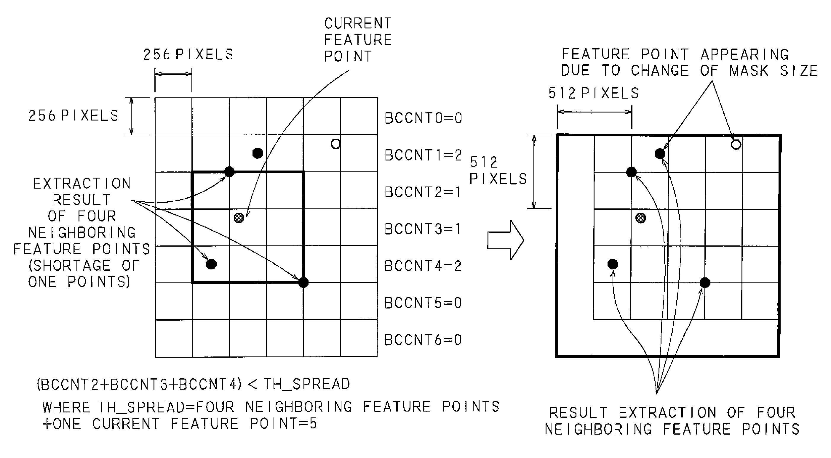
[0133]FIG. 23 is a flow chart showing a process procedure of a features calculating section 222 according to Example 3. The features calculating section 222 according to Example 3 sets a pixel block including one or a plurality of pixels of an image by the pixel block setting section 2220, and sets a mask size of the set pixel block (S501). The features calculating section 222 identifies, as a current feature point, one of the feature points extracted by the pixel block setting section 2220, sets, as a “surrounding region”, neighboring eight pixel blocks with the pixel block including the current feature point located in the center, and outputs data, including the set pixel block, mask size and surrounding region, to the neighboring point extraction section 2221.

[0134]The features calculating section 222 receives, at the neighboring point extraction section 2221, the data outputted from the pixel block setting section 2220, and extracts the neighboring feature points located within ...


PUM


Abstract

The number of pixels in an identified pixel region is counted, a feature point of the pixel region is extracted and the number of the feature points is counted when the number of the pixels counted has been determined to be equal to or higher than a first threshold value, whether the counted number of the feature points is equal to or lower than a second threshold value is determined, features is calculated based on the feature point extracted from the pixel region when the number of the feature points has been determined to be above the second threshold value, and the first threshold value is changed when the number of the feature points has been determined to be equal to or lower than the second threshold value. Image similarity determination process can be stably performed without any degradation in determination accuracy.

Description

CROSS-REFERENCE TO RELATED APPLICATIONS[0001]This Nonprovisional application claims priority under 35 U.S.C. §119(a) on Patent Application No. 2007-156719 filed in Japan on Jun. 13, 2007 and Patent Application No. 2008-127532 filed in Japan on May 14, 2008, the entire contents of which are hereby incorporated by reference.BACKGROUND OF THE INVENTION[0002]The present invention relates to an image processing method, an image processing apparatus, and an image forming apparatus for determining image similarity, and in particular relates to an image processing method, an image processing apparatus, and an image forming apparatus which are capable of improving the accuracy of determining similarity of images with a few feature points.[0003]Conventionally, there has been used a technique for comparing input image data, obtained by reading a document image using a scanner, with a stored image stored in advance to determine similarity therebetween, and for controlling, based on the determin...

Claims


Application Information

Patent Timeline
Patent Type & Authority Applications(United States)
IPC IPC(8): G06K9/46G06V30/10
CPCG06K9/4671G06V30/10G06V30/18143
Inventor YOSHINO, HIROKI
Owner SHARP KK
Learn More