
Method of fabricating an optical fiber preform using MCVD and nonlinear optical fiber fabricated using the method

a technology of optical fiber and preform, which is applied in the field of fabricating optical fiber preform, can solve the problems of reducing and deteriorating the functional characteristic imparted by the optical fiber doping, so as to achieve the effect of increasing the doping quantity of the dopan

Inactive Publication Date: 2005-05-24
OPTONEST CORPROATION +1
View PDF5 Cites 18 Cited by
  • Summary
  • Abstract
  • Description
  • Claims
  • Application Information

AI Technical Summary

Benefits of technology

[0024]Accordingly, the present invention has been made in an effort to solve the problems occurring in the related art, and it is an object of the present invention to provide a method of fabricating an optical fiber preform using a modified chemical vapor deposition method and a nonlinear optical fiber fabricated using the method, in which the core layer of the optical fiber preform can be uniformly doped with a dopant, and the doping quantity of the dopant can be increased.
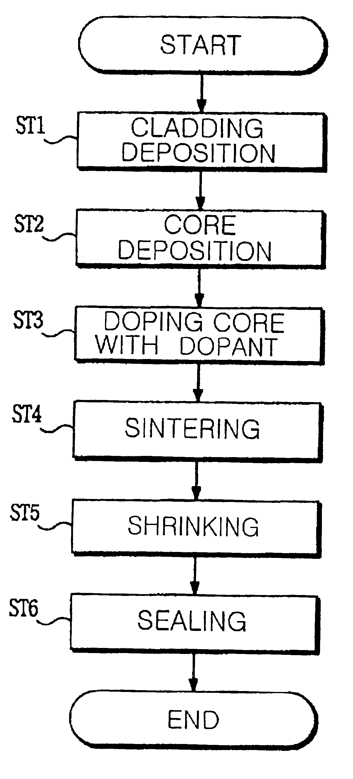
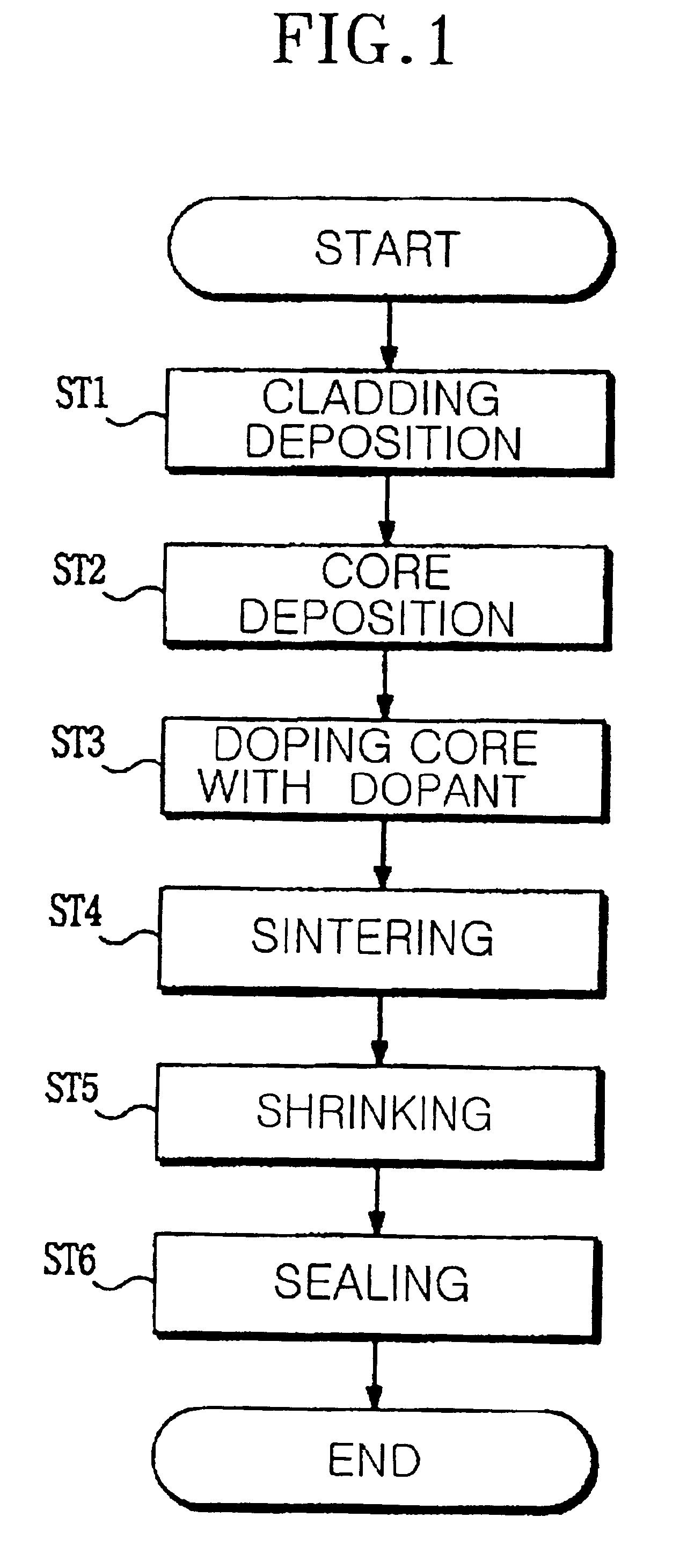
[0032]Namely, after shrinking the diameter of a quartz glass tube at both ends thereof, the sintered core layer is doped with a material containing a dopant, especially semiconductor fine particles of nano-size, so that the doping process can be stably executed by means of a conventional apparatus of fabricating an optical fiber perform without an additional apparatus, thereby making it possible to obtain a nonlinear optical fiber having stable characteristics. It is preferred that the dopant comprises at least one of PbTe, PbS, SnTe, CuCl, CdS, and CdSe.

Problems solved by technology

This results in deterioration of the functional characteristic imparted by the doping of the optical fiber perform, as shown in FIG.
However, in the conventional method of fabricating an optical fiber preform as described above, there is a difficulty in doping semiconductor fine particles of nano-size, which is larger than that of existing dopants.
Further, the doping apparatus as described above limits the sintered portion of the core layer, and thus limits doping quantity of the dopant.
This adversely affects the characteristic of a functional optical fiber, especially that of the non-linear optical fiber, which is influenced by the doping quantity of the dopant.

Method used


Image

  • Method of fabricating an optical fiber preform using MCVD and nonlinear optical fiber fabricated using the method
  • Method of fabricating an optical fiber preform using MCVD and nonlinear optical fiber fabricated using the method
  • Method of fabricating an optical fiber preform using MCVD and nonlinear optical fiber fabricated using the method

Examples


first embodiment

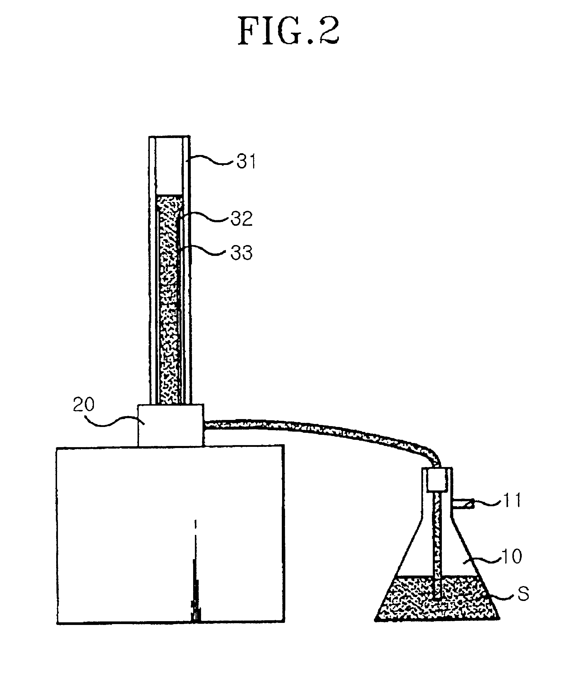
[0046]FIG. 4 is a constructional view of an apparatus of fabricating an optical fiber preform using MCVD according to the present invention.

[0047]As shown in FIG. 4, in the apparatus of fabricating an optical fiber preform, a quartz glass tube 52 is held by a lathe 51, heated at a portion 53 by a heating device 54. For example, the quartz glass tube 52 is rotated in a first direction 55a, and the heating device 54 is moved in a second direction 55b by a carrier member 56. That is, the heated portion 53 of the quartz glass tube 52 is moved while being rotated.

[0048]In the meantime, a material, preferably solution, containing a substance, especially semiconductor fine particles of a few nano-size for forming a functional optical fiber perform, is injected from a material supplier 58 through an injection tube 57 into the quartz glass tube 52. In this case, the semiconductor fine particles injected into the quartz glass tube 52 from the material supplier 58 include particles consisting ...


PUM

PropertyMeasurementUnit
Diameteraaaaaaaaaa
Nonlinear systemaaaaaaaaaa

Abstract

A method of fabricating an optical fiber preform using a modified chemical vapor deposition method and a nonlinear optical fiber fabricated using the method. The method comprises the steps of: forming a cladding layer and a core layer in a quartz glass tube; partially sintering the core layer; partially shrinking both ends of the quartz glass tube, in which the cladding layer and the core layer partially sintered are formed; and doping a sintered portion of the core layer with an impurity component, so that the optical fiber preform fabricated has a predetermined function. The nonlinear optical fiber being fabricated by a process comprising the steps of: forming the cladding layer and the core layer in a quartz glass tube; partially sintering the core layer; partially collapsing both ends of the quartz glass tube; and doping a sintered portion of the core layer with a predetermined impurity component.

Description

BACKGROUND OF THE INVENTION[0001]1. Field of the Invention[0002]The present invention relates to a method of fabricating an optical fiber preform using a modified chemical vapor deposition method and a nonlinear optical fiber fabricated using the method, in which the optical fiber is provided with a specific function by adding a particular dopant.[0003]2. Description of the Related Art[0004]An optical fiber utilized in optical communications is an element, in which light is transmitted by means of total reflection due to a difference of optical refractive indices between a cladding portion, which is made from quartz glass of high purity, and a core portion, in which elements such as germanium (Ge) are added to silica glass to slightly heighten the optical refractive index.[0005]In general, the process of fabricating the optical fiber is further divided into a process of fabricating an optical fiber preform and a process of drawing an optical fiber from the optical fiber preform. The...

Claims


Application Information

Patent Timeline
IPC IPC(8): C03B37/018G02B6/13G02B6/132G02B6/136C03B37/014C03C13/04
CPCC03B37/01838C03B37/01861G02B6/136C03C13/04G02B6/132C03B2201/58B82Y30/00C03B37/018
Inventor HAN, WON-TAEKCHO, JUNG-SIK
Owner OPTONEST CORPROATION
Learn More