Filtrate monitoring device, and filtrate monitoring system

a monitoring device and filtering technology, applied in the direction of instruments, membranes, separation processes, etc., can solve the problems of difficult automation, high construction cost, large scale, etc., and achieve the effect of stably performing image measurement, easy to specify, and easy detection through an imag

Active Publication Date: 2010-04-22
HIRATA & CO LTD
View PDF3 Cites 17 Cited by
  • Summary
  • Abstract
  • Description
  • Claims
  • Application Information

AI Technical Summary

Benefits of technology

[0039]In accordance with the present invention, for example, when particle weight in the flow channel exceeds a given value and a value of the turbidity meter exceeds a predetermined value, the particle measurement utilizing an image may be started such that it is not necessary to perform image measurement all the time. Generally, a turbidity meter is to measure an absolute value of macro particle amount in the flow channel in which the flow rate is relatively high, and image measurement in the flow channel in the observation plate of the observation cell is to measure a state of individual particles at the micro level. Accordingly, because it is not necessarily efficient to perform measurement of all the water samples taken from the membrane filtration water-purifying apparatus by the image measurement serving as micro measurement means, macro measurement means can be complemented with this. Macro particle measurement is capable of capturing partially existing particles that are present unevenly in the flow channel depending on the way of setting a preset value. On the other hand, in the micro particle measurement, a portion of the sampled water in which no particles exist may be measured depending on the way of sampling. In such a case, it is determined whether or not there are particles by the macro particle measurement. Thereafter, the water is concentrated so as to increase the ratio of those particles accounted in the sampled water, which enables the micro measurement to measure particles even in the partially sampled water. By performing the micro particle measurement even for an extremely small amount of flowing water, it is possible to stably perform the image measurement even in a case where particles are dispersed unevenly or the amount of particles is extremely low in the flowing water.
[0040]Further, when the filtration film is ruptured, broken pieces of the filtration film which are generated and / or objects supposed to be removed by filtration (those which the unbroken original filtration film traps) flow out so as to be included as impurities in the flow channel of the filtrate water pipe line system. Some of those are trapped and accumulated at a dam of the observation bath of the observation cell inside the branch filtrate water pipe line system, which can be detected and analyzed to be identified through an image detection by a camera. However, it is difficult to identify only the broken pieces in the case where other objects than the broken pieces exist in the flow channel at the same time. It becomes easier to specify the broken pieces if the broken pieces and the other impurities can be respectively separated and observed in the observation baths of a plurality of corresponding observation cells.
[0041]As differences between the broken pieces and the other impurities, dimensions (sizes), densities, shapes, and the like of the objects are named. And, the sizes of impurities to be trapped are considered to be substantially determined depending on the size of a dam (step) provided in the observation bath of the observation cell. By utilizing this characteristic, detection through an image is made easier by providing the dam (step) in a size comparable to the sizes of the impurities to be trapped.
[0042]Further, provided that an observation bath of the observation cell having a dam (step) which is capable of trapping impurities in other sizes than broken pieces of the film is provided upstream, and an observation bath having a dam (step) which is capable of trapping impurities such as broken pieces is provided downstream, the other impurities than the broken pieces are eliminated upstream, and the flowing water including only the broken pieces pass through the inside of the observation bath downstream, which makes it possible to more precisely detect an image of the broken pieces.
[0043]Generally, the size of target broken pieces is 2 μm which is the smallest among those of impurities, and it is possible to achieve the above-described object by providing observation baths having dams (steps) (for example, 10 μm and 20 μm) that trap impurities in sizes greater than the smallest size upstream thereof.
[0044]Further, in the case where sizes of broken pieces differ depending on the types thereof, the broken pieces may be sorted out by the size as a plurality of dams (steps) having different sizes are provided, thereby enabling the measurement to detect images according to individual sizes.

Problems solved by technology

There are issues with such equipment that the equipment tends to be large in scale, a construction cost thereof is high, automation thereof is difficult, operation and management thereof are not easy, many chemicals such as aggregating agents are added thereto, it is difficult to improve water quality, and so on.
However, those are implemented as the operation of the membrane filtration water-purifying system is temporarily stopped such that it is not possible always to monitor the water.
Further, in case that impurities in the flow channel of the filtrate water pipe line system is too few, or that impurities are unevenly dispersed in the flow channel, it may not be possible to shoot and analyze images therein.
Further, those are not designed for detecting damage to the filtration film, and configurations thereof are different.
Then, it is difficult to identify ruptured pieces of the film since images including various sizes of mixed impurities are detected when the film is broken.

Method used


Image

  • Filtrate monitoring device, and filtrate monitoring system
  • Filtrate monitoring device, and filtrate monitoring system
  • Filtrate monitoring device, and filtrate monitoring system

Examples


embodiment 1

[0109]A filtrate water monitoring apparatus of Embodiment 1 is used for detecting damage to a filtration film (a filtration medium) set in the membrane filtration water-purifying apparatus to monitor its performance degradation (caused by damage or its lifetime) in order to ensure the safety of filtrate water discharged from a membrane filtration water-purifying apparatus used for purifying any type of water source including natural water such as river water, lake water, or groundwater. This filtration film may be, for example, a hollow-fiber membrane module. However, the filtration film is not limited to the hollow-fiber membrane module.

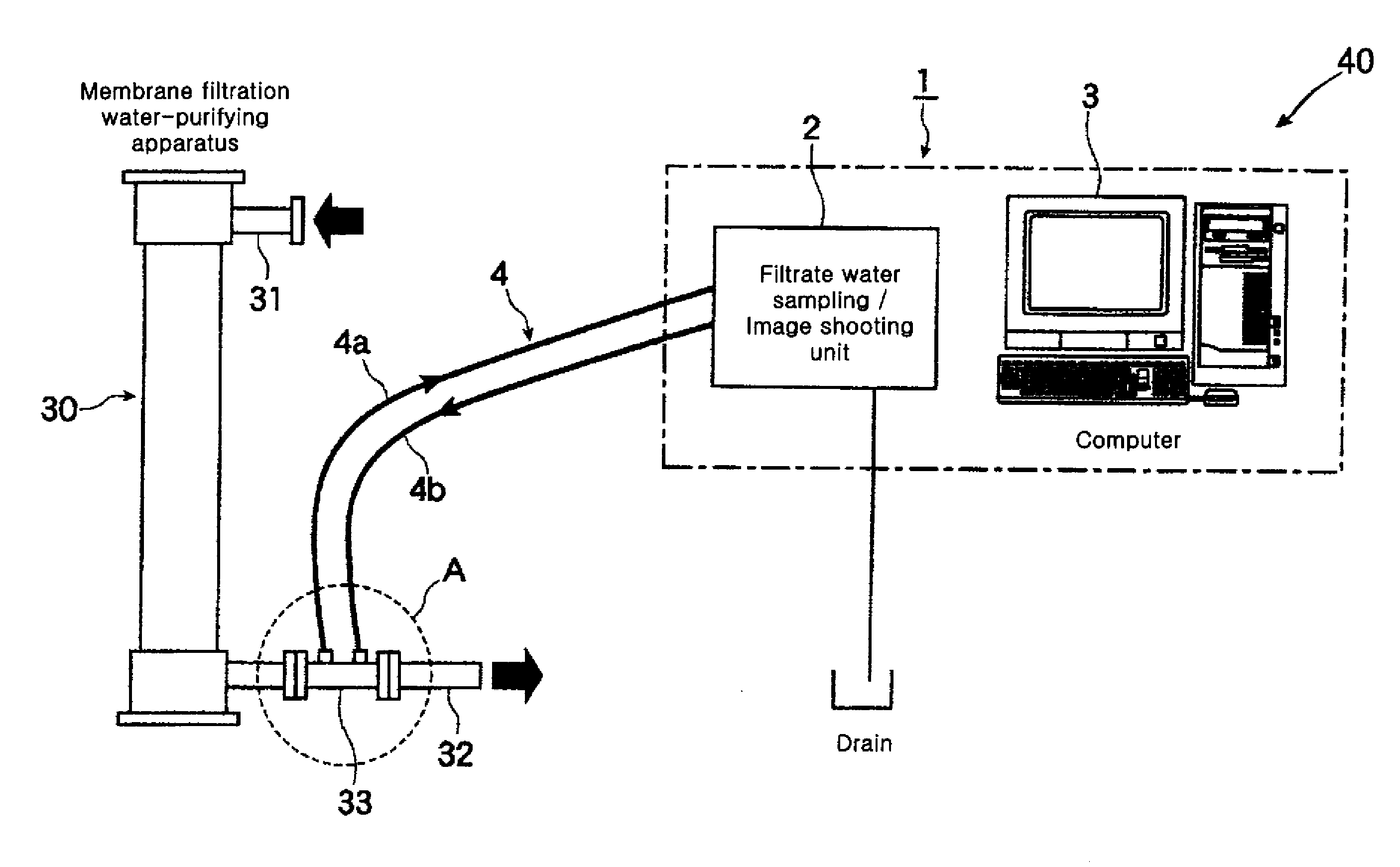
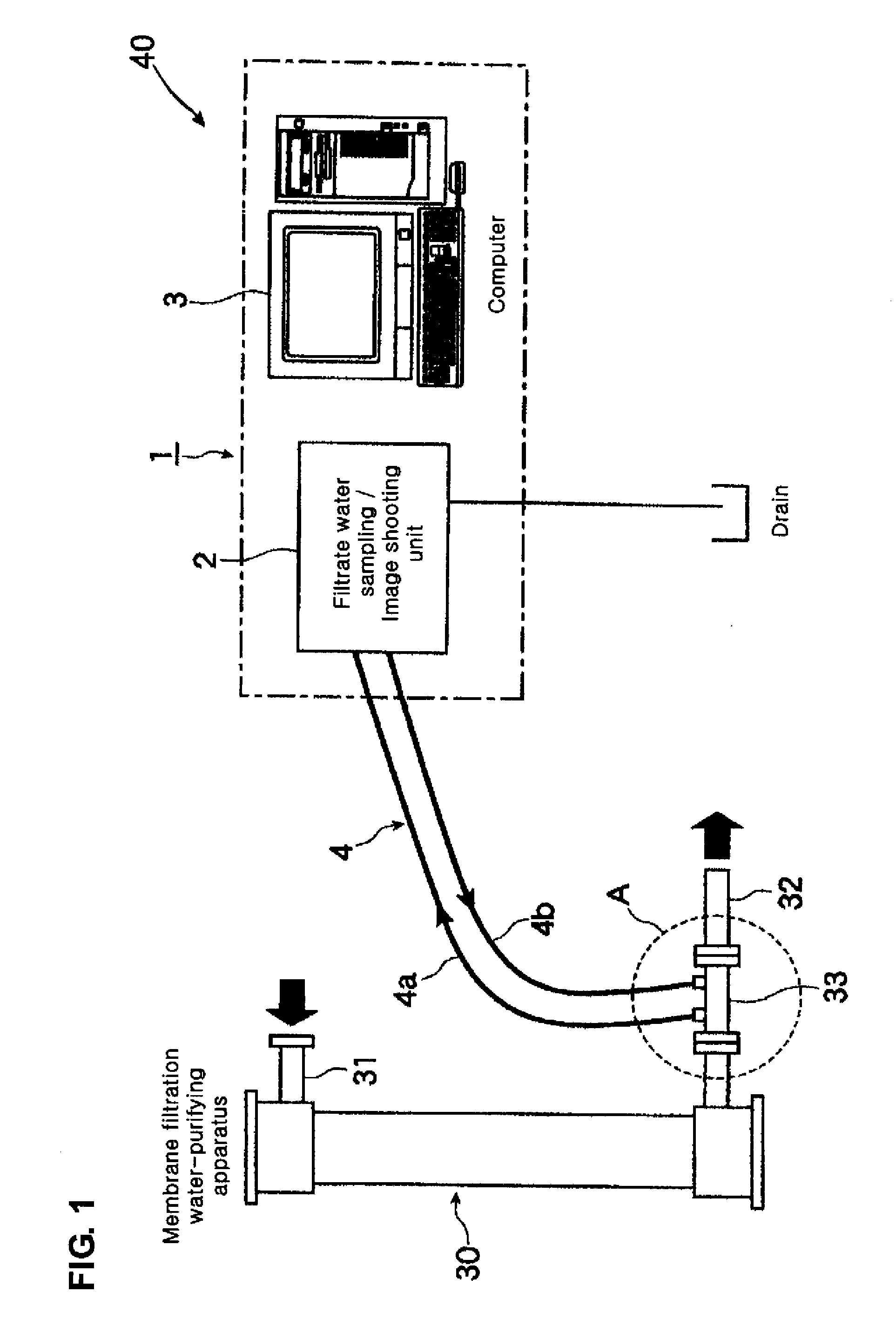
[0110]As shown in FIG. 1, a filtrate water monitoring apparatus 1 includes a filtrate water sampling / image shooting unit 2 and an image analysis unit 3 that analyzes an image of filtrate water obtained by the filtrate water sampling / image shooting unit 2 to identify impurities included in the filtrate water. The filtrate water sampling / image shootin...

embodiment 2

[0132]FIG. 9 is a diagram schematically showing Embodiment 2 of the present invention. Redundant descriptions with Embodiment 1 will be omitted. In the same way as in Embodiment 1, the filtrate water pipe line system 4 is made to branch from a main pipe (main line) through which filtrate water filtrated through the water supply pipe line system 31 passes. A gate valve 150 is set in the filtrate water pipe line system 4, and the gate valve 150 prevents the filtrate water from passing through the filtrate water pipe line system 4 or adjusts a flow amount of filtrate water. Here, a flow rate of approximately 100 ml / min is provided. The filtrate water pipe line system 4 is further made to branch into a branch line 142 having a throttle valve 140, and a gate valve 152 is installed in the main pipe of the filtrate water pipe line system 4, and the filtrate water is directly discharged out of the system when the gate valve 152 is open.

[0133]The filtrate water in the pipe 142 made to branch...

embodiment 3

[0135]FIG. 10 is a diagram schematically showing Embodiment 3 of the present invention. Redundant descriptions with those in Embodiment 1 or 2 will be omitted. The filtrate water pipe line system 4 is made to branch from the main pipe (main line) through which filtrate water filtrated through the water supply pipe line system 31 passes in the same way as in Embodiments 1 and 2. The gate valve 150 and the throttle valve 151 are installed in the filtrate water pipe line system 4, that prevent the filtrate water from passing through the filtrate water pipe line system 4 or adjust a quantity of the filtrate water. Here, a flow rate of 100 ml / min is provided.

[0136]Next, a turbidity meter 160 in a laser transmitted light measurement method is provided. The turbidity meter 160 measures a situation of turbidity by measurement using a laser beam before detecting an image of sample water in the flow channel of the branched filtrate water pipe line system 4. It is possible to sense occurrence ...


PUM

PropertyMeasurementUnit
sizeaaaaaaaaaa
widen angleaaaaaaaaaa
diametersaaaaaaaaaa

Abstract

A filtrate monitoring device and a filtrate monitoring system, which can monitor a membrane-type water filtrating / purifying system at all times and which can flexibly adjust themselves to the contents and sizes of impurities, are provided. The filtrate monitoring device monitors the filtrate having passed through the membrane-type water filtrating / purifying device. The filtrate monitoring device comprises: imaging / detecting means for shooting images in the filtrate having passed through the filtrating / purifying device, on the filtrate flowing in an observation bath of a filtrate observing cell disposed midway of the branched filtrate pipeline, thereby to specify the particles contained in the filtrate, and / or optical detecting means disposed midway of the filtrate pipeline before or after branching.

Description

FIELD OF THE INVENTION [0001]The present invention relates to a membrane filtration water-purifying apparatus in order to purify water from any type of water source including river water, lake water, or groundwater, and to a filtrate water monitoring apparatus and a filtrate water monitoring system in a membrane filtration water-purifying system.BACKGROUND ART[0002]As water-purifying equipment for filtrate plants that purifies natural water into clean water, water-purifying equipment in which coagulation settling tanks and sand filtration equipment are combined have been conventionally used in a large number of applications. There are issues with such equipment that the equipment tends to be large in scale, a construction cost thereof is high, automation thereof is difficult, operation and management thereof are not easy, many chemicals such as aggregating agents are added thereto, it is difficult to improve water quality, and so on. Recently, various membrane filtration water-purif...

Claims


Application Information

Patent Timeline
Patent Type & Authority Applications(United States)
IPC IPC(8): G01N15/02
CPCB01D61/20B01D65/102B01D2311/06B01D2311/24C02F1/008C02F1/44G01N2015/0693C02F2209/005C02F2209/11G01N15/0227
Inventor MURAKAMI, SEIGOHIRAKAWA, TAKENORIISERI, TAKAFUMI
Owner HIRATA & CO LTD
Why Eureka
Try Eureka