Integrated command center for flat screen televisions, and internet protocol monitors

a command center and flat screen technology, applied in the field of flat screen televisions and internet protocol monitors, can solve the problems of increasing inconvenient installation, unsightly appearance, and difficult installation, and achieve the effect of reducing the time to market, streamlined and cost-efficient production chain, and reducing the service cost associated with the implementation of service to the customer

Inactive Publication Date: 2009-01-29
REIN GARY
View PDF27 Cites 0 Cited by
  • Summary
  • Abstract
  • Description
  • Claims
  • Application Information

AI Technical Summary

Benefits of technology

[0012]The rapidly changing features, and delivery technologies, have been necessitating continual hardware upgrades, and therefore difficulties in accurate production quantity projections. By creating a single Command Center, the inventory obsolescence, and component waste is also radically reduced, thereby creating a streamlined, cost-efficient production chain.
[0013]Furthermore, the distribution, time to market, and service costs associated with the implementation of service to the customer is also radically reduced, creating significant cost efficiencies in this highly competitive marketplace.
[0014]End-user advantages include: significant space efficiency by utilizing a single command center unit, multi-tier add-on menu driven price options, and overall ease of use associated with a single consolidated unit.

Problems solved by technology

This type of installation functioned well over several decades, but has become increasingly inappropriate, unsightly, and difficult to install with the increasing use of flat screen televisions which are designed primarily for wall mounting.
A second problem with the standard set-top box is that it was designed only to provide a television signal to the consumer.

Method used


Image

  • Integrated command center for flat screen televisions, and internet protocol monitors
  • Integrated command center for flat screen televisions, and internet protocol monitors
  • Integrated command center for flat screen televisions, and internet protocol monitors

Examples


Embodiment Construction

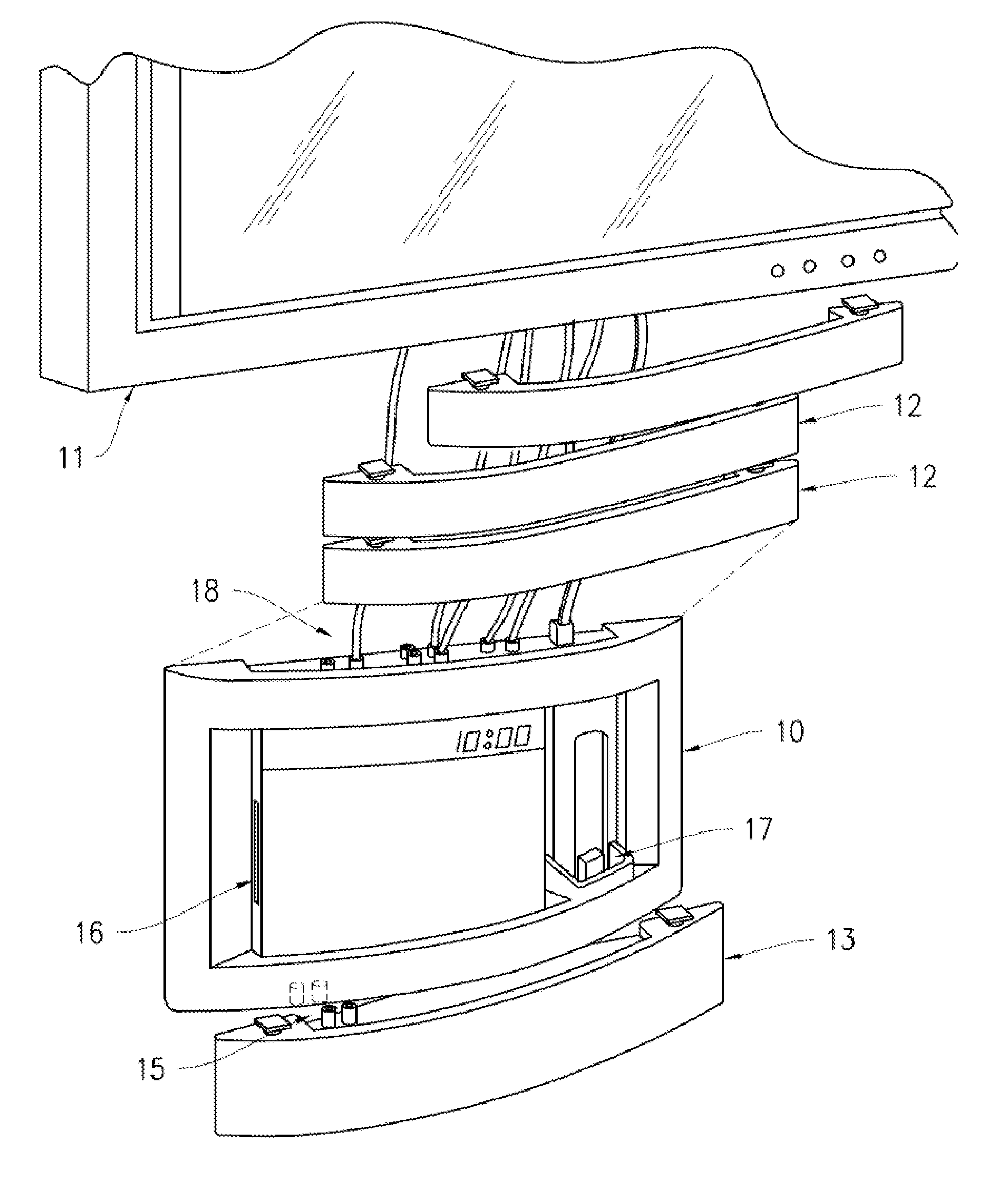
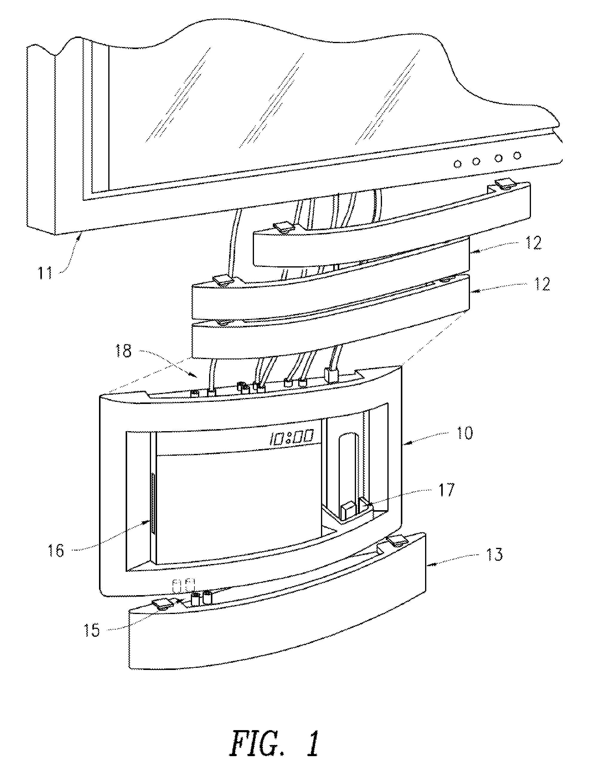
[0019]Referring now to FIG. 1, there is shown a view of the invention and how it is used in conjunction with a flat screen television.

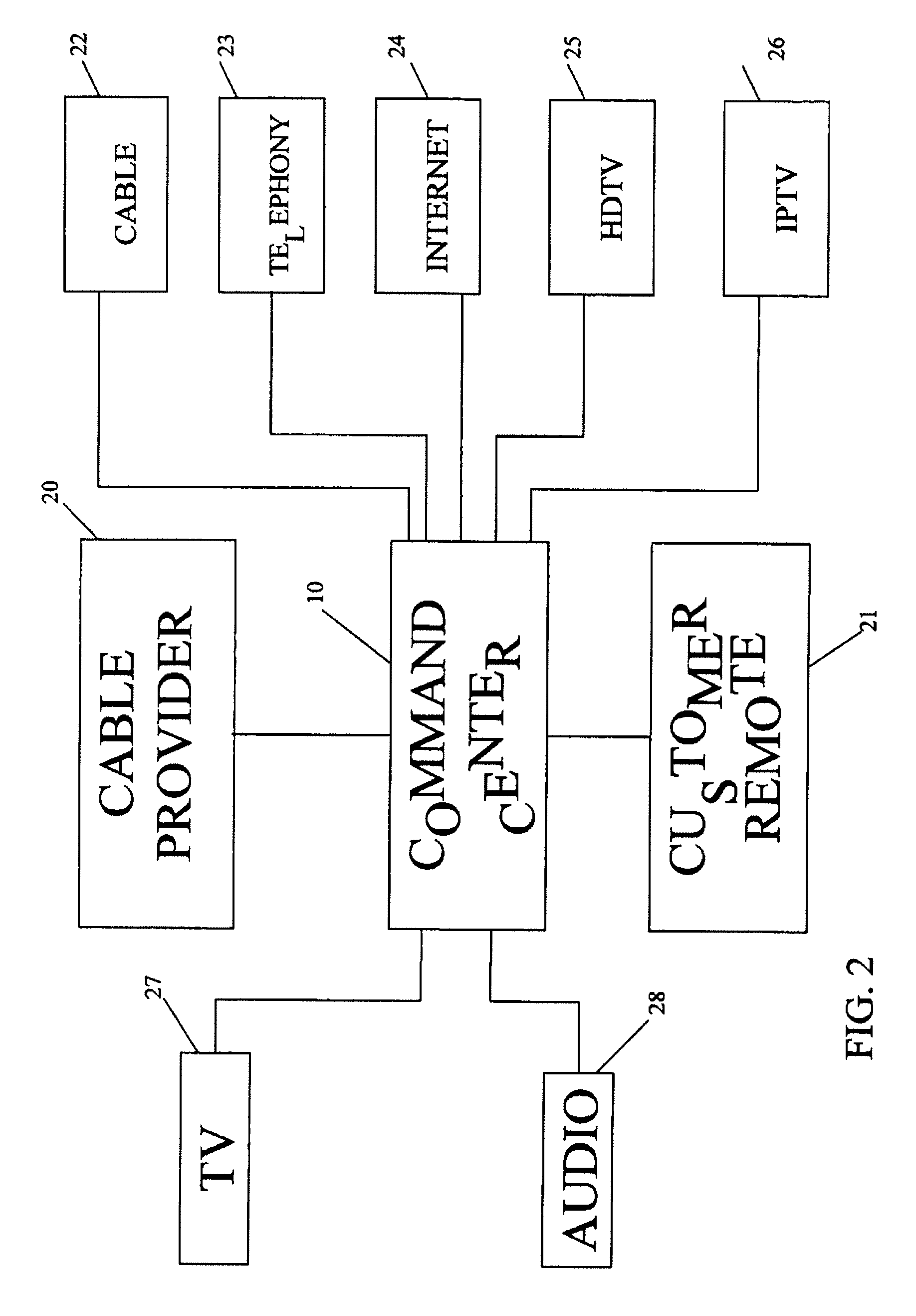
[0020]More particularly, the Command Center shown at 10 replaces the standard set-top box and accommodates a plurality of incoming information signals as will be described below. The Command Center can also accommodate a DVD / DVR player (or Blu-ray player with the disc slot shown at 16, as well as an i-Pod docking nest shown at 17.

[0021]Hardwire connection terminals on Command Center 10 are shown at 18, which allows the Command Center to be connected to flat screen television 11. The actual wires extending from the Command Center 10 to flat screen television 11 will be hidden from view by one or more hollow modular cowls shown at 12. It is to be understood that for this embodiment of the invention, flat screen television 11 is wall-mounted with Command Center 10 wall mounted below the flat screen television. The number of modular cowls required for a p...


PUM


Abstract

A wall mountable media control system locatable adjacent a wall mounted video screen comprising a wall mountable media control center capable of controlling a plurality of different types of information data and having at least one output connection for each of said different types of information data for connection of wiring from said wall mountable media control center to said wall mounted video screen, at least one of said plurality of different types of information data being selectively enableable by a service provider of said information data, said plurality of different types of information data being accessible by command of a user of said wall mountable media control center; a plurality of wall mountable cowls locatable between said wall mountable media control center and said wall mounted video screen, said plurality of wall mounted cowls being sized and shaped to cover said wiring connecting said wall mountable media control center and said wall mounted video screen, said plurality of wall mountable cowls being interconnectable with one another by integral connection components; and a modular information data receiver addition connectable to said wall mounted media control center, said modular information data receiver addition adapted to receive information data not initially receivable by said wall mountable media control center.

Description

CROSS REFERENCE TO RELATED APPLICATIONS[0001]This is a continuation-in-part of application Ser. No. 11 / 519,304, filed Sep. 11, 2006, which application is related to and claims the benefit of, under 35 USC § 119(e), U.S. Provisional Patent Application Ser. No. 60 / 835,404, filed Aug. 2, 2006.FIELD OF THE INVENTION[0002]The present invention relates to enhancing the capability and appearance of flat screen televisions, and IP Monitor installations and more particularly to a command center which remotely enables a plurality of incoming information signals that are controlled from a central station, while eliminating the disadvantages in function, and appearance of the standard cable set-top box.BACKGROUND OF THE INVENTION[0003]It is well known that the communications industry is consolidating. Where once there were separate providers for television, telephone and the internet, today all three communication media are often supplied by a single provider. This is especially true for the ca...

Claims


Application Information

Patent Timeline
Patent Type & Authority Applications(United States)
IPC IPC(8): H04N5/64
CPCG06F1/16G06F2200/1631H04N5/44H04N21/42646H04N5/775H04N5/85H04N5/64
Inventor REIN, GARY
Owner REIN GARY
Why Eureka
Try Eureka