
Thin film magnetic head structure, method of making same and thin film magnetic head

a thin film, magnetic head technology, applied in the direction of electrical transducers, instruments, record information storage, etc., can solve the problems of uneven length of main magnetic pole layer uneven width of magnetic pol

Active Publication Date: 2009-02-05
HEADWAY TECH INC
View PDF18 Cites 1 Cited by
  • Summary
  • Abstract
  • Description
  • Claims
  • Application Information

AI Technical Summary

Benefits of technology

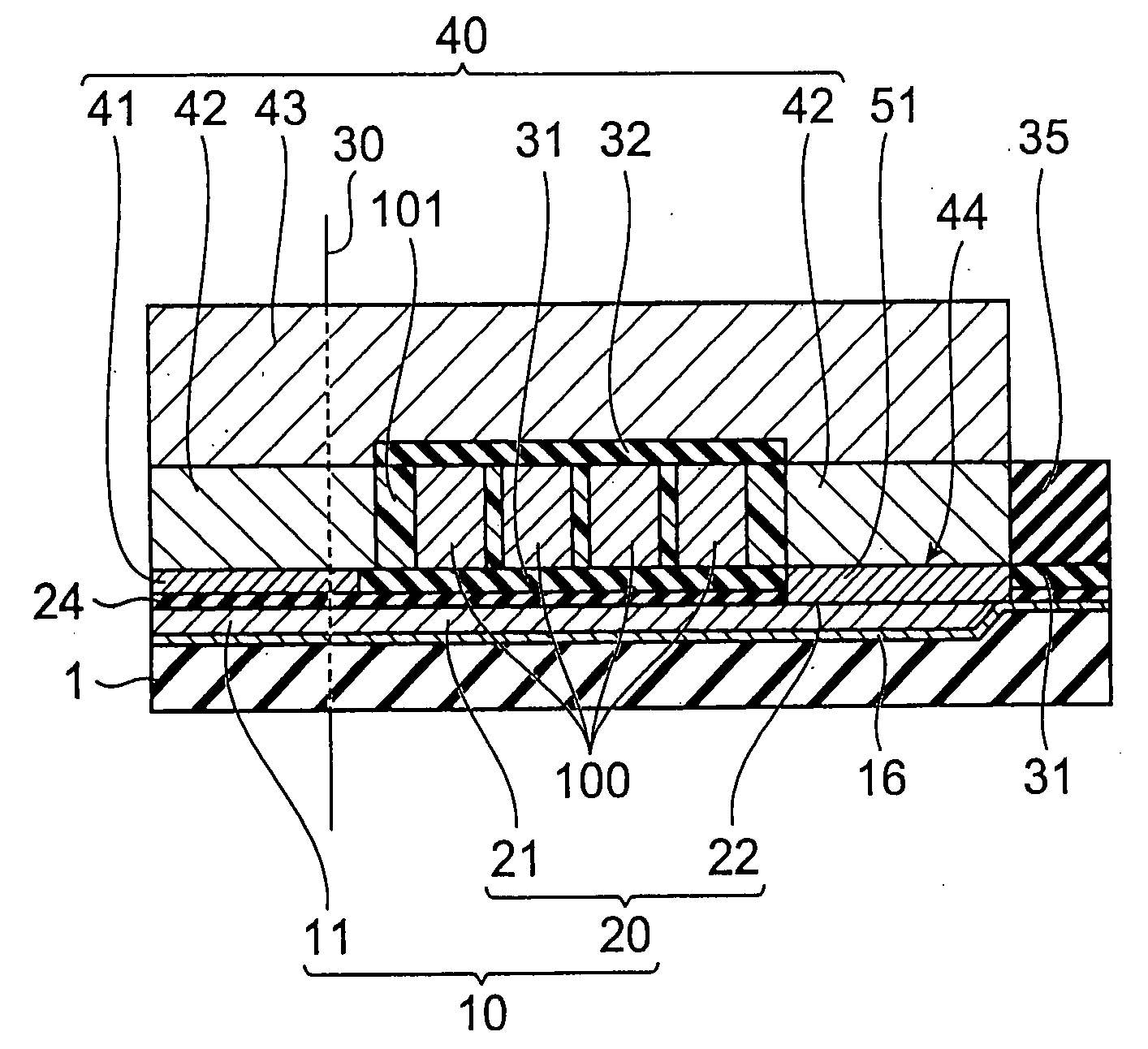
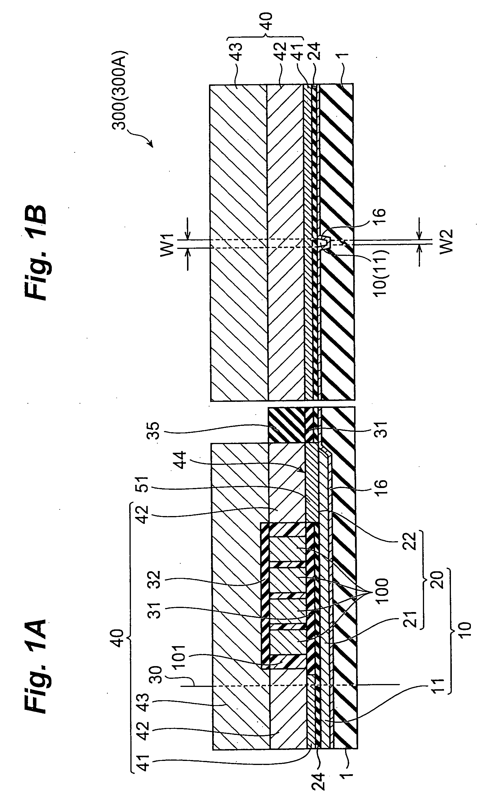
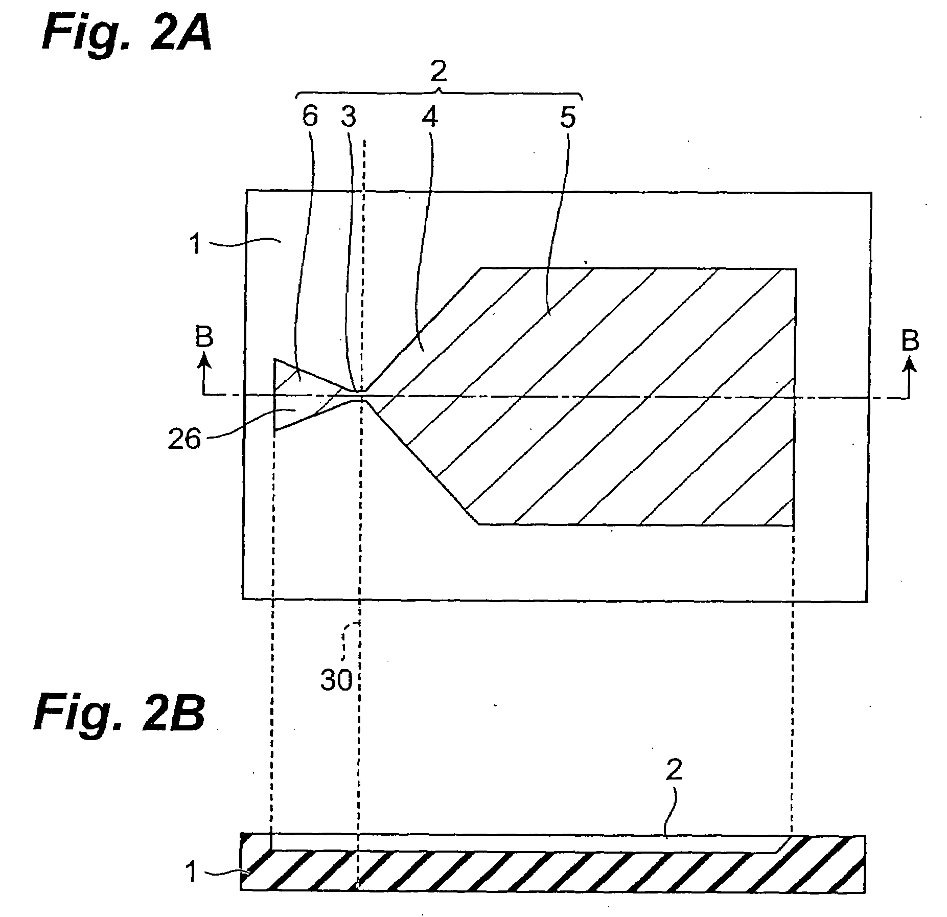
The present invention provides a thin-film magnetic head structure that can control track width with high accuracy. The main magnetic pole layer includes a magnetic pole tip with an even width portion, which ensures that the ABS (air bearing surface) has the same width when cut at different positions. This eliminates the issue of uneven width in the ABS among products. The thin-film magnetic head structure also includes a base insulating layer with a magnetic pole forming depression, which helps to fill the narrow groove part of the depression and prevent pole erasure. The even width portion of the magnetic pole tip is 0.3 μm to 1.2 μm long and has a width of 0.2 μm or less. The method of manufacturing the thin-film magnetic head structure involves forming the magnetic pole tip with an even width portion and a write shield layer to prevent pole erasure. Overall, the present invention provides a solution for improving the track width control and manufacturing a thin-film magnetic head with high accuracy.

Problems solved by technology

In PMRs in which the magnetic pole tip on the ABS side in the main magnetic pole layer has a bevel form, the width of the magnetic pole (hereinafter referred to as tip width) is not sufficiently uniform and thus is uneven along the length of the main magnetic pole layer.

Method used


Image

  • Thin film magnetic head structure, method of making same and thin film magnetic head
  • Thin film magnetic head structure, method of making same and thin film magnetic head
  • Thin film magnetic head structure, method of making same and thin film magnetic head

Examples


modified examples

[0126]Without being restricted to the above-mentioned embodiment, the present invention can be modified in various manners.

modified example 1

[0127]The above-mentioned manufacturing process of the thin-film magnetic head structure can be modified as follows. Namely, after the whole upper face of the substrate is subjected to CMP as explained with reference to FIGS. 12A and 12B, the thin-film coil 100 is formed by way of the insulating layer 31 earlier than the second shield part 42. Subsequently, the photoresist 101 is formed so as to cover the thin-film coil 100. Further, the second shield part 42 is formed so as to cover the thin-film coil 100 and the photoresist 101, and connect with the first shield part 41 and the back magnetic pole layer 51. This yields a thin-film magnetic head structure 301 including the write shield layer 40 comprising the first shield part 41 and second shield part 42 without the third shield part 43 as shown in FIGS. 26A and 26B.

[0128]This thin-film magnetic head structure 301 has the same configuration as with the thin-film magnetic head structure 300 except that it lacks the third shield part...

modified example 2

[0129]A nonmagnetic film 61 may be interposed between the magnetic pole tip 11A and yoke magnetic pole layer 20A forming the above-mentioned end face junction as in a thin-film magnetic head structure 310 shown in FIG. 27. The nonmagnetic film 61 is formed in a portion of the yoke magnetic pole part 20 other than its surface on the thin-film coil 100 side. Namely, the nonmagnetic film 61 is disposed at the interface 14 between the magnetic pole tip 11 and the yoke magnetic pole part 20, and in the portion between the yoke magnetic pole part 20 and the coating 16. The nonmagnetic film 61 is made of Ru, Ta, W, Cr, NiPd, or the like and has a thickness of about 10 to 30 Å.

[0130]The nonmagnetic film 61 functions to control the direction of remnant magnetization mr in the magnetic pole tip 11 and yoke magnetic pole part 20 and prevent the direction of remnant magnetization mr from being oriented in a different direction. Therefore, the thin-film magnetic head structure 310 can more effec...


PUM

PropertyMeasurementUnit
depthaaaaaaaaaa
depthaaaaaaaaaa
bevel angleaaaaaaaaaa

Abstract

A thin-film magnetic head structure has a configuration adapted to manufacture a thin-film magnetic head configured such that a main magnetic pole layer including a magnetic pole tip on a side of a medium-opposing surface opposing a recording medium, a write shield layer opposing the magnetic pole tip so as to form a recording gap layer on the medium-opposing surface side, and a thin-film coil wound about the write shield layer or main magnetic pole layer are laminated. The magnetic pole tip of the main magnetic pole layer includes an even width portion having a substantially even width along an extending direction.

Description

[0001]This application is a divisional of U.S. patent application Ser. No. 10 / 985,891, filed Nov. 12, 2004, the entire contents of which are hereby incorporated by reference.BACKGROUND OF THE INVENTION[0002]1. Field of the Invention[0003]The present invention relates to a thin-film magnetic head structure for manufacturing a thin-film magnetic head which performs magnetic recording operations by perpendicular recording, a method of manufacturing the same, and a thin-film magnetic head.[0004]2. Related Background Art[0005]In recent years, the areal density in hard disk drives has been increasing remarkably. Recently, the areal density in hard disk drives has reached 160 to 200 GB / platter in particular, and is about to increase further. Accordingly, thin-film magnetic heads have been required to improve their performances.[0006]In terms of recording schemes, thin-film magnetic heads can roughly be divided into those for longitudinal recording in which information is recorded in a (lon...

Claims


Application Information

Patent Timeline
Patent Type & Authority Applications(United States)
IPC IPC(8): G11B5/33
CPCG11B5/1278G11B5/3116Y10T29/49046Y10T29/49048G11B5/3163
Inventor SASAKI, YOSHITAKAARAKI, HIRONORIITO, HIROYUKI
Owner HEADWAY TECH INC
Learn More