Device Having a Shape Memory Element

a technology of shape memory and device, applied in the direction of machines/engines, generators/motors, magnetic bodies, etc., can solve the problem of unfavorable mechanical stress conditions

Inactive Publication Date: 2009-02-05
ROBERT BOSCH GMBH
View PDF1 Cites 17 Cited by
  • Summary
  • Abstract
  • Description
  • Claims
  • Application Information

AI Technical Summary

Benefits of technology

[0010]In addition, it may be advantageous if a coupler is provided which compensates for different thermal expansions of components of the

Problems solved by technology

The disadvantage is that, because of the selected positioning of metallic elements and air gaps, the magnetic field excited around the electric coil develops at most a slight magnetic f

Method used


Image

  • Device Having a Shape Memory Element
  • Device Having a Shape Memory Element
  • Device Having a Shape Memory Element

Examples


Embodiment Construction

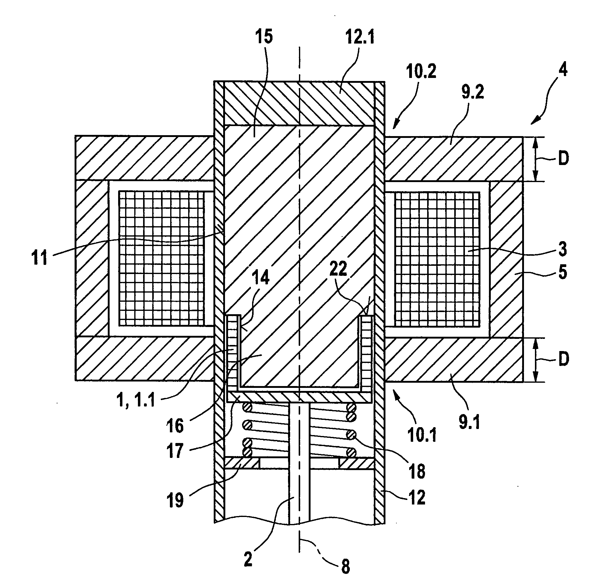
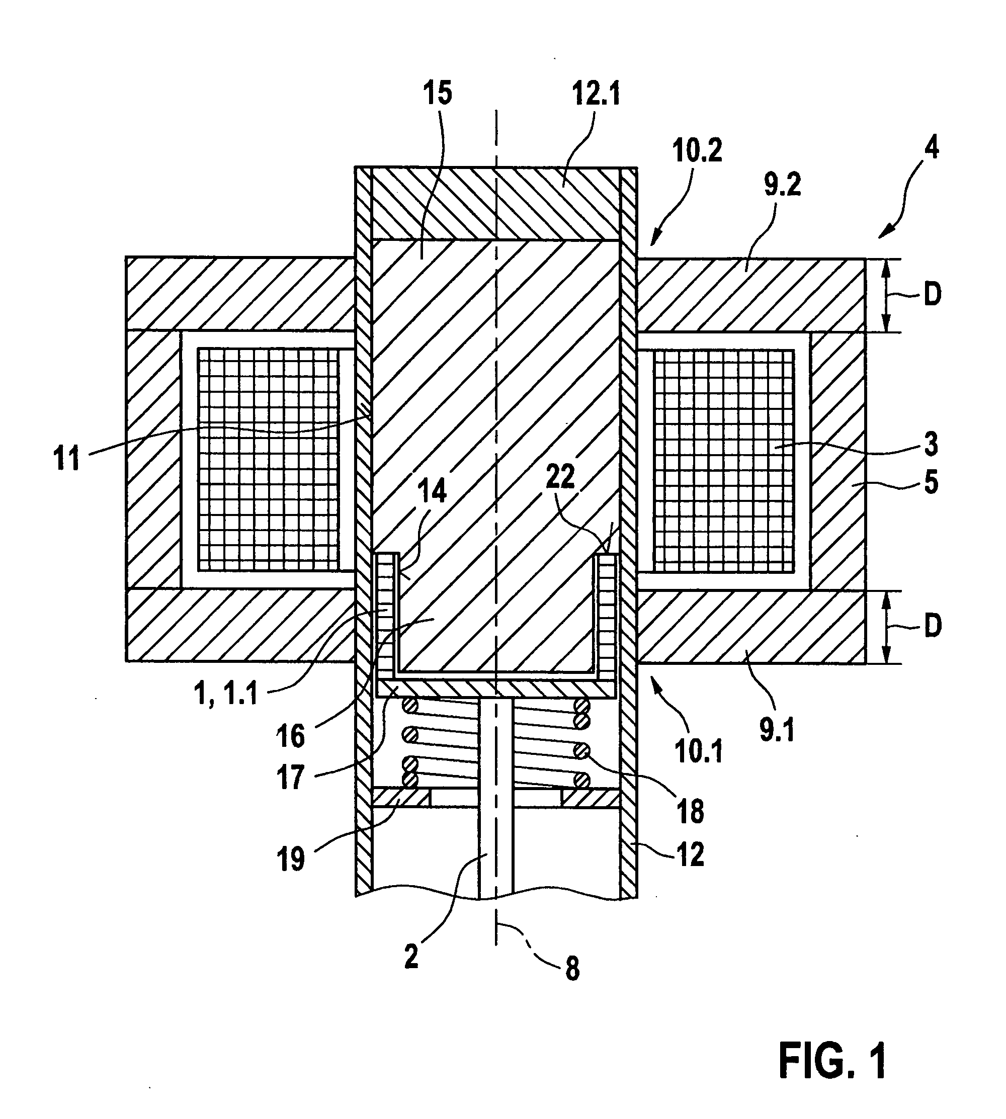
[0019]FIG. 1 shows a simplified view of a first exemplary embodiment of a device according to the present invention, having an actuator and a shape memory element. The device is used to operate the actuator using the lift of the shape memory element. The device is, for example, any valve, for instance, a fuel injector valve, and the actuator is a valve needle or a valve pin.

[0020]The example device according to the present invention has at least one shape memory element 1, which as an actuator operates an assigned actuator 2. The at least one shape memory element 1 is made up of a so-called shape memory alloy, for instance, a magnetic shape memory alloy.

[0021]When a magnetic field is applied, shape memory element 1 carries out a control stroke travel operating actuator 2, by contracting in the direction of the magnetic lines of force of the magnetic field and expanding in a direction transverse to the magnetic lines of force. A third direction remains neutral. According to the first...


PUM


Abstract

Conventional devices have a valve needle and a shape memory element which, by the application of a controllable magnetic field, executes a control stroke travel that operates the actuator, and having a coil that excites the magnetic field which is situated in a magnet housing which, at its end face, is bordered with respect to an actuating axis by a front wall in each case, the front walls having a through opening radially within the coil. It is a disadvantage that the magnetic field excited around the coil is conducted unfavorably, so that at most a slight magnetic field develops in the shape memory element. The shape memory element has a magnetic field flowing through it, in the direction of its longitudinal extension, if at all. Since the shape memory element has a high magnetic resistance and is developed to be very long in the axial direction, only a very weak magnetic field can be induced in the shape memory element. In response to the magnetic field that is weak at most, the shape memory element can generate only a very slight lift of the valve needle. In the device according to the present invention, a strong magnetic field is conducted through the shape memory elements, and in this way, a large control stroke travel is achieved. The shape memory element(s) is/are positioned generally only in the through opening(s).

Description

FIELD OF THE INVENTION[0001]The present invention relates to a device having a shape memory.BACKGROUND INFORMATION[0002]A device is described in JP 2001280215 A which has a valve needle and a shape memory element that, by the application of a controllable magnetic field, carries out a control stroke travel that operates the valve needle, and a coil that excites the magnetic field, which is situated in a magnet housing which is limited at its end face with respect to its actuating axis by a front wall, in each case, the two front walls having a through opening within the coil. The control stroke travel is achieved by the shortening of the shape memory element in the direction of a actuating axis of the valve needle. The disadvantage is that, because of the selected positioning of metallic elements and air gaps, the magnetic field excited around the electric coil develops at most a slight magnetic field in the shape memory element. The shape memory element has a magnetic field flowing...

Claims


Application Information

Patent Timeline
IPC IPC(8): H02N2/02
CPCF02M51/0603H01L41/12F02M2200/22F02M61/08H10N35/00
Inventor HOANG, ANH-TUANMAIER, MARTINHOHL, GUENTHER
Owner ROBERT BOSCH GMBH
Why Eureka
Try Eureka