Fifth generation x-ray computed tomography system and operating method

a computed tomography and x-ray technology, applied in the field of ct system, can solve the problems of affecting the positioning of the variable focus, the running speed of the focus must correspond, and the simple filter design that has a rotationally symmetrical design over the entire extent is less suitable, so as to achieve the effect of quick change of the focus position

Inactive Publication Date: 2009-02-05
SIEMENS HEALTHCARE GMBH
View PDF11 Cites 17 Cited by
  • Summary
  • Abstract
  • Description
  • Claims
  • Application Information

AI Technical Summary

Benefits of technology

The invention provides a fifth generation CT system and method that does not use a rotating x-ray tube and detector, but allows for optimal focus-side filtering and collimation, as well as possible detector-side collimation. The system can quickly change the position of the focus while maintaining its effectiveness.

Problems solved by technology

The technical problem addressed in this patent is to improve the filtering, collimation, and scatter radiation suppression of a fifth generation CT system without being limited by the rotation speed of the support frame and the focus position.

Method used


Image

  • Fifth generation x-ray computed tomography system and operating method
  • Fifth generation x-ray computed tomography system and operating method
  • Fifth generation x-ray computed tomography system and operating method

Examples


Embodiment Construction

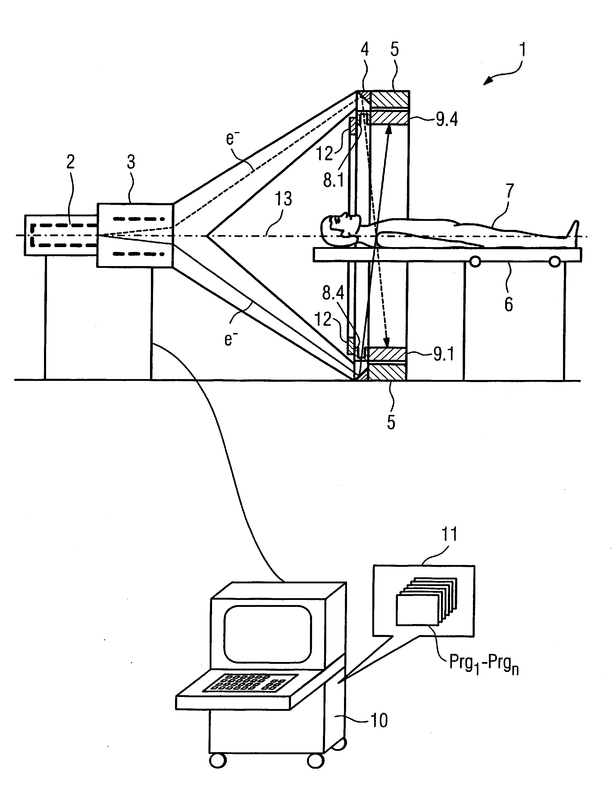
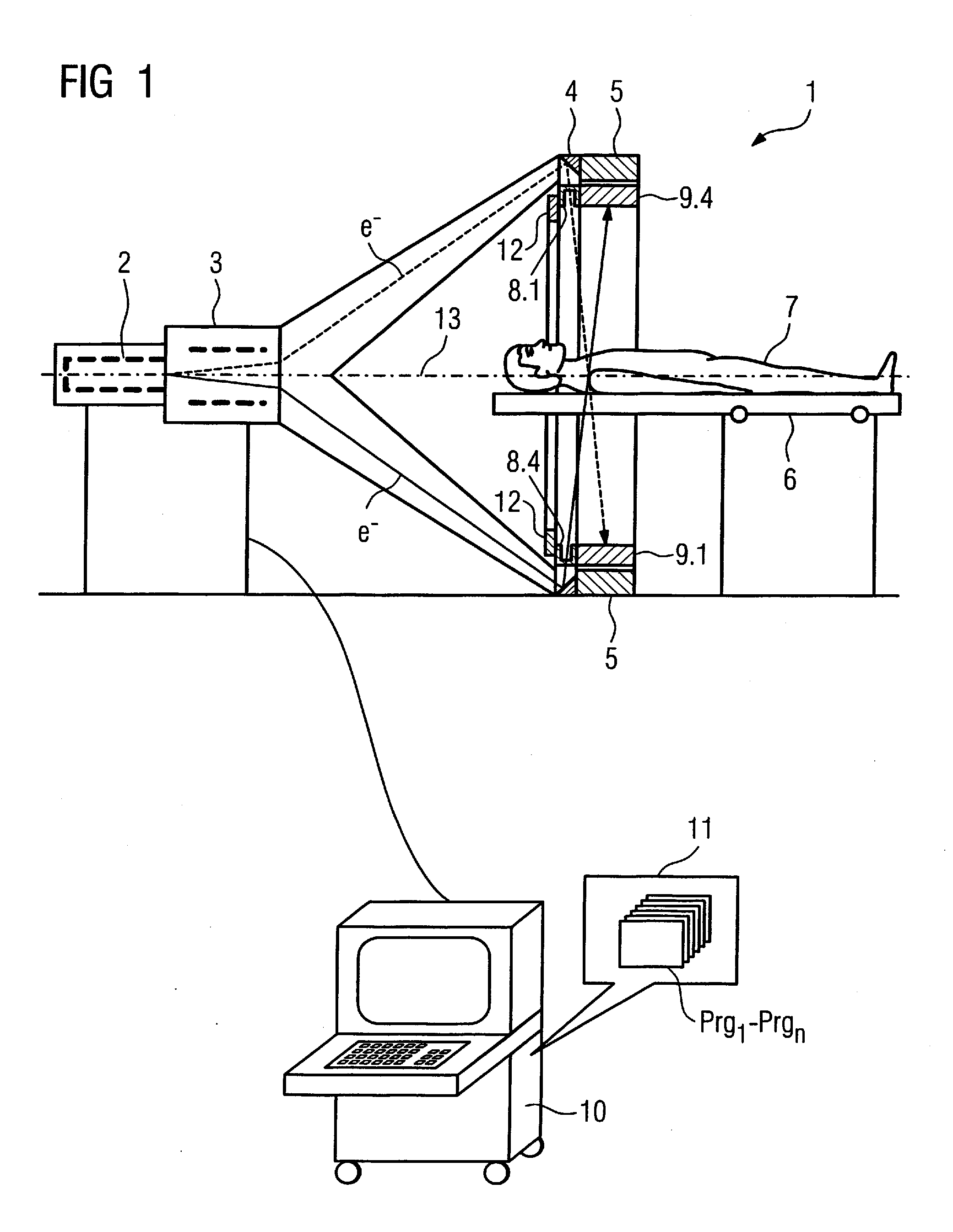
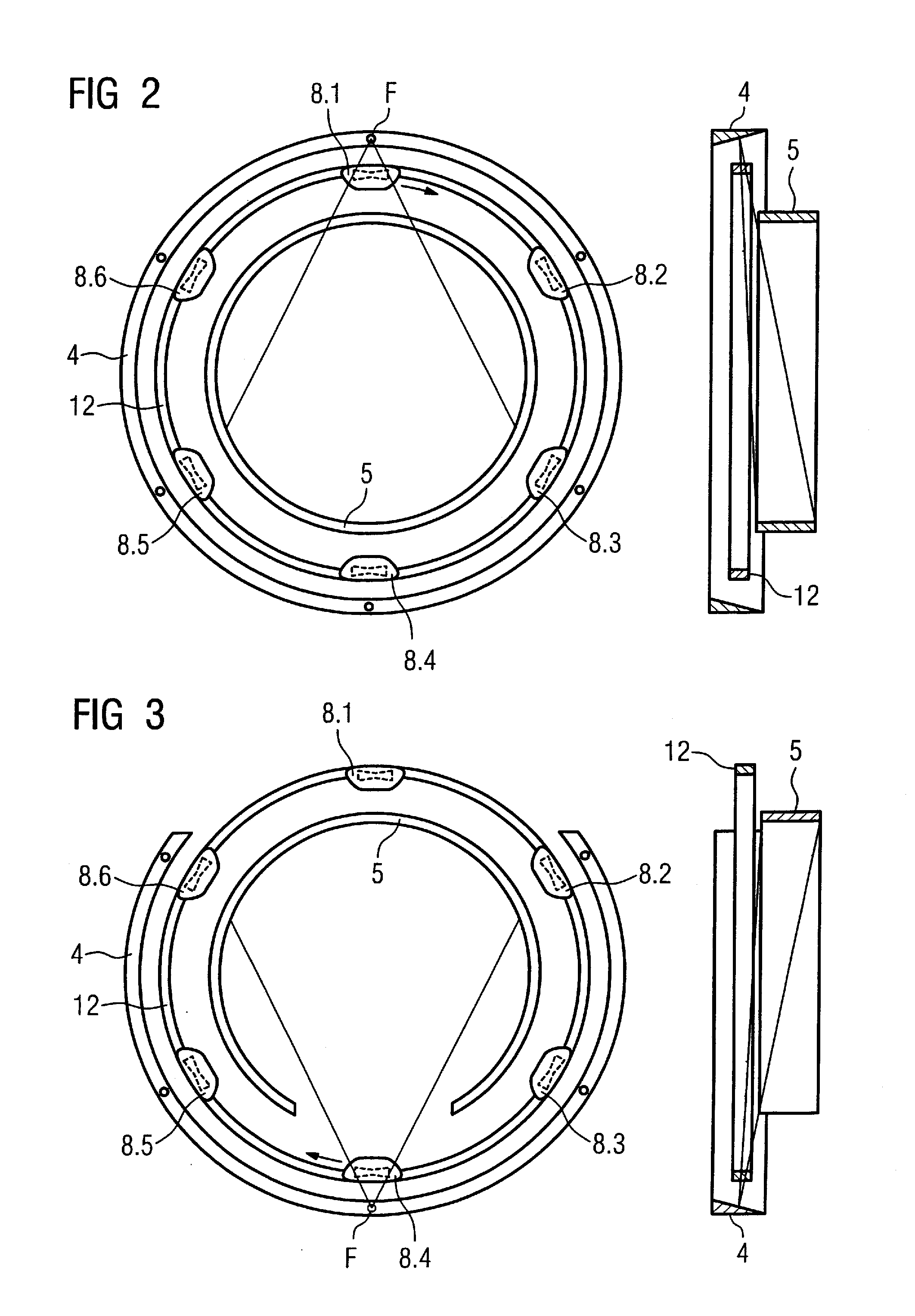
[0033]In the following the invention is described in detail using preferred exemplary embodiments with the aid of figures, wherein only the features necessary for comprehension of the invention are shown. The following reference characters are used: 1: fifth generation x-ray computed tomography system; 2: electron beam emitter; 3: deflection system; 4: stationary anode ring; 5: stationary detector ring; 6: displaceable patient bed; 7: patient; 8.1 through 8.6: filter sets on support frame; 8.1.1: bowtie filter; 8.1.2, 8.1.3: phi-filter; 9.1, 9.4: detector-side collimators / scatter radiation filters; 10: control and computer system; 11: memory space in the computer system; 12: rotatable support frame; 13: system axis; 14: scattered radiation filter; I, II: sectors of the stationary anode ring; EI, EII: anode ring sectors with different x-ray energies; F: focus; e−: electrons; γ: x-ray radiation; φ: fan angle; z: z-axis.

[0034]FIG. 1 shows an exemplary fifth generation x-ray computed to...


PUM


Abstract

A fifth generation x-ray computed tomography system has at least one electron beam generator that generates at least one electron beam, an anode ring or partial anode ring arranged concentrically around a system axis, from which x-ray radiation can be generated at a number of focus positions by striking the ring or partial ring with the at least one electron beam, a detector ring or partial detector ring arranged concentrically around the system axis, with a number of detector elements forming at least one detector row to detect the impinging x-ray radiation; and a rotatable support frame on which filter and collimator elements are carried. The filter and collimator elements are arranged at the focus on the support frame at at least two positions that are angularly offset relative to one another.

Description


Claims


Application Information

Patent Timeline
Owner SIEMENS HEALTHCARE GMBH
Why Eureka
Try Eureka