Thrust cylindrical roller bearing

Active Publication Date: 2009-02-05
NSK LTD
View PDF2 Cites 4 Cited by
  • Summary
  • Abstract
  • Description
  • Claims
  • Application Information

AI Technical Summary

Benefits of technology

[0068]According to the invention that is configured as has been described above, the thrust cylindrical roller bearing can be realized which facilitates the design to secure load-carrying capacity, facilita

Problems solved by technology

Furthermore, an oil film for lubrication becomes difficult to be formed at this mutual rubbing portion, and a metal contact becomes easy to occur at the mutual rubbing portion.
In the event that drilling wear like this occurs, the sliding resistance of the roller end face relative to the cage is increased, which increases the rotational resistance of the rotary supporting portion in which the thrust cylindr

Method used


Image

  • Thrust cylindrical roller bearing
  • Thrust cylindrical roller bearing
  • Thrust cylindrical roller bearing

Examples


Example

Embodiment 1

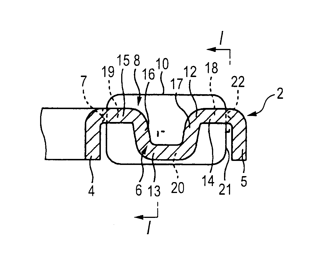
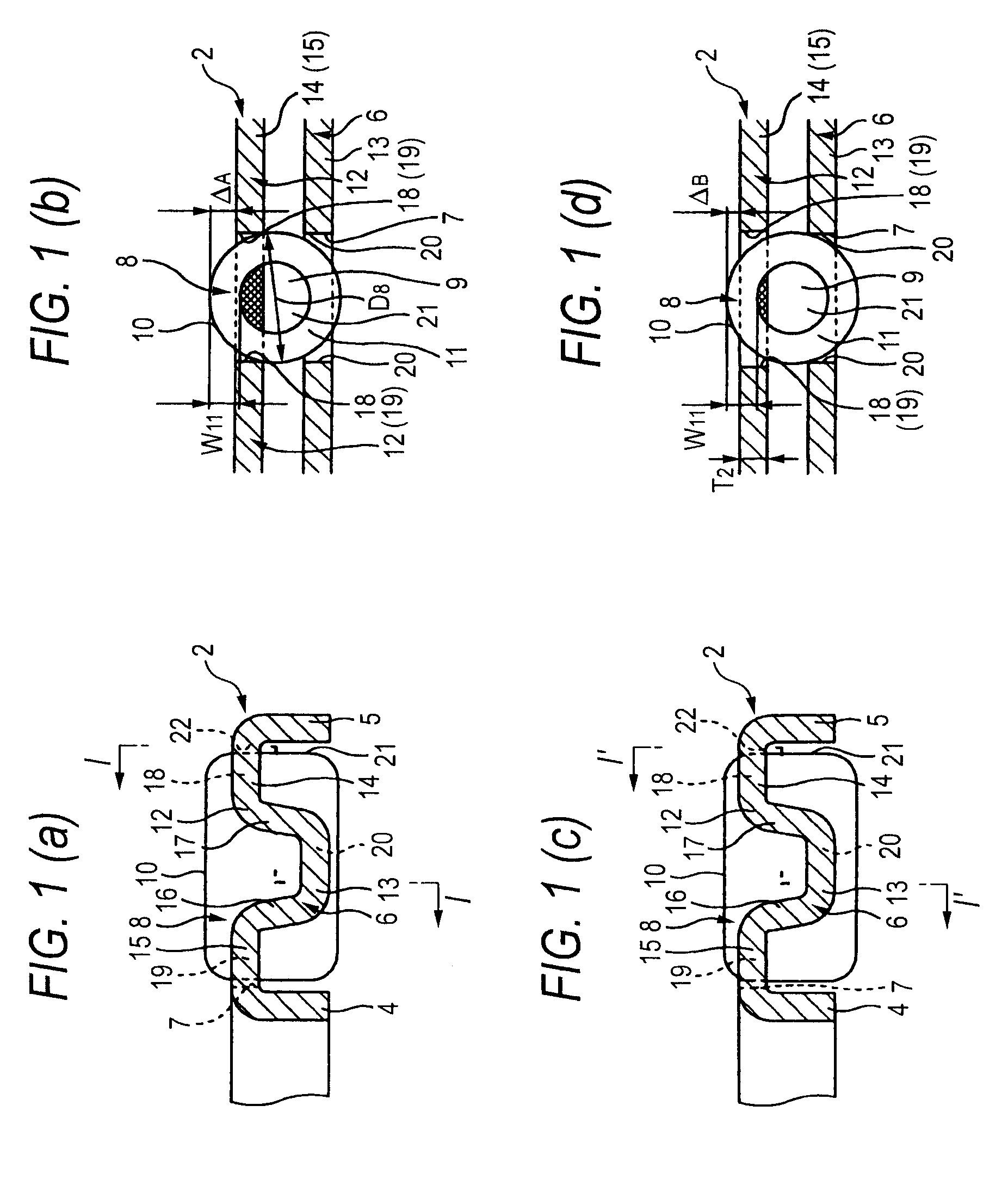
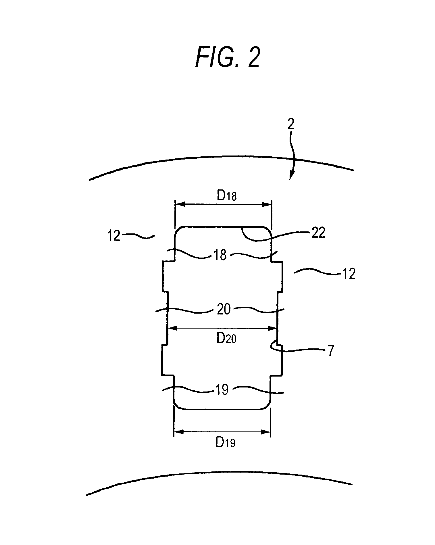
[0119]FIGS. 1 to 2 show Embodiment 1 of the invention which corresponds to the first and fifth inventions. Note that a feature of this embodiment resides in a fact that even though a cylindrical roller in which a central flat surface 9 is provided at a central portion of axial end faces thereof is used as each of cylindrical rollers 8, the occurrence of wear such as leads to the concavely recessed portion 23 shown in FIG. 20 described above at an outside diameter side circumferential edge portion 22 of each of a plurality of pockets 7 provided in a radial direction in an intermediate plate portion 6 which makes up a cage 2 is prevented by controlling the movement of each cylindrical roller 8 within each pocket 7 in relation to a diameter dimension (the diameter of the central flat surface 9 formed at the central portion) of chamfered portions 11 which are formed at portions on both the axial end faces of each cylindrical roller 8 which lie closer to an outside diameter s...

Example

Embodiment 2

[0130]FIG. 4 shows Embodiment 2 of the invention which corresponds to the first to second inventions. Note that a feature of this embodiment also resides in a fact that even though a cylindrical roller in which a central flat surface 9 is provided at a central portion of axial end faces thereof is used as each of cylindrical rollers 8, the occurrence of wear such as leads to the concavely recessed portion 23 shown in FIG. 20 described above at an outside diameter side circumferential edge portion 22 of each of a plurality of pockets 7 provided in a radial direction in an intermediate plate portion 6 which makes up a cage 2 is prevented by controlling the movement of each cylindrical roller 8 within each pocket 7 in relation to a diameter dimension (the diameter of the central flat surface 9 formed at the central portion) of chamfered portions 11 which are formed at portions on both the axial end faces of each cylindrical roller 8 which lie closer to an outside diameter s...

Example

Embodiment 3

[0132]FIGS. 5 to 7 show Embodiment 3 of the invention which corresponds to the first to third inventions. Note that a feature of this embodiment resides in a fact that even though a cylindrical roller in which a central flat surface 9a is provided at a central portion of axial end faces thereof is used as each of cylindrical rollers 8b, the occurrence of such wear as leads to the concavely recessed portion 23 shown in FIG. 20 described above at an outside diameter side circumferential edge portion 22 of each of a plurality of pockets 7 provided in a radial direction in an intermediate plate portion 6 which makes up a cage 2 is prevented by controlling the configuration and dimensions of chamfered portions 11a, 11a formed on both the axial end faces of each cylindrical roller 8b at a portion lying closer to an outside diameter side thereof in relation to the movement of each cylindrical roller 8b within each pocket 7. Since the configuration and function of the other port...


PUM


Abstract

A diameter dimension of a chamfer 11 which is formed on axial end faces of a cylindrical roller 8 which is retained in each pocket 7 of a cage 2 whose axial positioning is realized by a roller guide at a portion which lies closer to an outside diameter side thereof is made such that a central flat surface 9 which lies on an inside diameter side of the chamfer 11 is not exposed from an external surface of an outside diameter side flat plate portion 14. Then, a difference between a minimum value ΔB of an amount by which the cylindrical roller 8 projects from the external surface of the outside diameter side flat plate portion 14 and a dimension W11 of the chamfer 11 with respect to a diameter direction thereof is made smaller than a thickness T2 of the cage 2.

Description

TECHNICAL FIELD[0001]The present invention relates to an improvement in thrust cylindrical roller bearings which are built in rotary supporting portions of various types off machines such as automotive transmissions, compressors for automotive air conditioners and machine tools. More particularly, the invention relates to an improvement in thrust cylindrical roller bearings which each include a cage which can be produced at low costs by the application of press-cutting process and bending process to a single sheet of metal, in which a construction having a superior durability is realized by reducing wear of the cage. Note that thrust cylindrical roller bearings to which the invention is applied include thrust needle bearings which use as rolling elements needles (needle-like rollers) whose axial dimension is larger than outside-diameter dimension. Consequently, cylindrical rollers which are described in this specification and claims attached thereto include the needles.BACKGROUND AR...

Claims


Application Information

Patent Timeline
IPC IPC(8): F16C33/54
CPCF16C19/30F16C33/541F16C2240/40F16C33/546
Inventor LIU, JUNYAMADA, RYOSUKEKOBAYASHI, KOUJIOTANI, AZUSA
Owner NSK LTD
Why Eureka
Try Eureka