
Quick assembly blade for a ceiling fan (2)

a ceiling fan and quick assembly technology, applied in the field of ceiling fans, can solve the problems of unstable structure of the blade engagement, inability to secure the blade frame with stability, and swinging to disable the ceiling fan to rotate smoothly and stably, so as to keep integrity and external beauty of the ceiling fan, and quick assembly

Active Publication Date: 2009-02-05
AIR COOL INDAL
View PDF4 Cites 0 Cited by
  • Summary
  • Abstract
  • Description
  • Claims
  • Application Information

AI Technical Summary

Benefits of technology

[0006]The objective of this invention is to offer a quick assembly blade for a ceiling fan, including a blade frame, a blade and a press board. The blade frame is fixed thereon with at least three studs extending upward, spaced apart and respectively locked thereon with a fastener to be inserted in both the insert hole of the blade and the engage hole of the press board, with the head of the fastener inserted out of the upper side of the insert hole of the blade and the lower portion of the fastener engaged with the engage hole of the press board. Further, the blade is bored with a positioning hole at a location among the insert holes, and each engage hole of the press board has its rear end expanded and formed with a receiving hole with a comparatively large diameter. The press board is further disposed with an elastic stopper protruding downward at a location corresponding to the positioning hole of the blade, and having a stop member provided at the front end. By so designing, when the press board is pushed to move backward horizontally and fixedly pressed on the blade with a large area, the blade can be quickly assembled on the blade frame, able to reinforce the combined stability of the press board with the blade and the blade frame. In addition, after assembling of the blade, the elastic stopper of the press board is stuck on the inner wall of the positioning hole of the blade and hidden therein, able to keep integrity and external beauty of the ceiling fan.

Problems solved by technology

Although the blade of the conventional ceiling fan can be quickly assembled on the blade frame by mutual engagement of the engage holes of the blade and the studs of the blade frame, the structure of their engagement is unstable and the blade cannot be secured on the blade frame with stability.
Under the circumstances, when the ceiling fan is driven to rotate, the blades are likely to be loosened and cause swing to disable the ceiling fan to rotate smoothly and stably.
In addition, after the blade and the blade frame are assembled together, the elastic stop strip is positioned at the outside of the front end of the blade visibly exposed out, thus spoiling integral beauty of the blade of the ceiling fan.

Method used


Image

  • Quick assembly blade for a ceiling fan (2)
  • Quick assembly blade for a ceiling fan (2)
  • Quick assembly blade for a ceiling fan (2)

Examples


Embodiment Construction

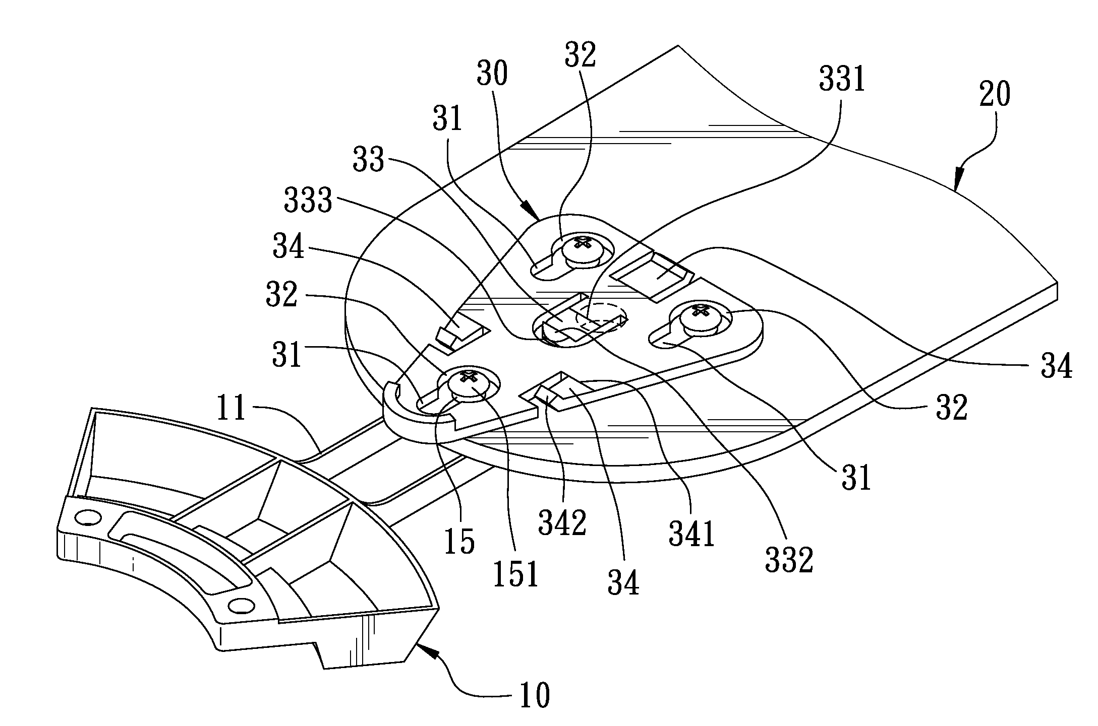
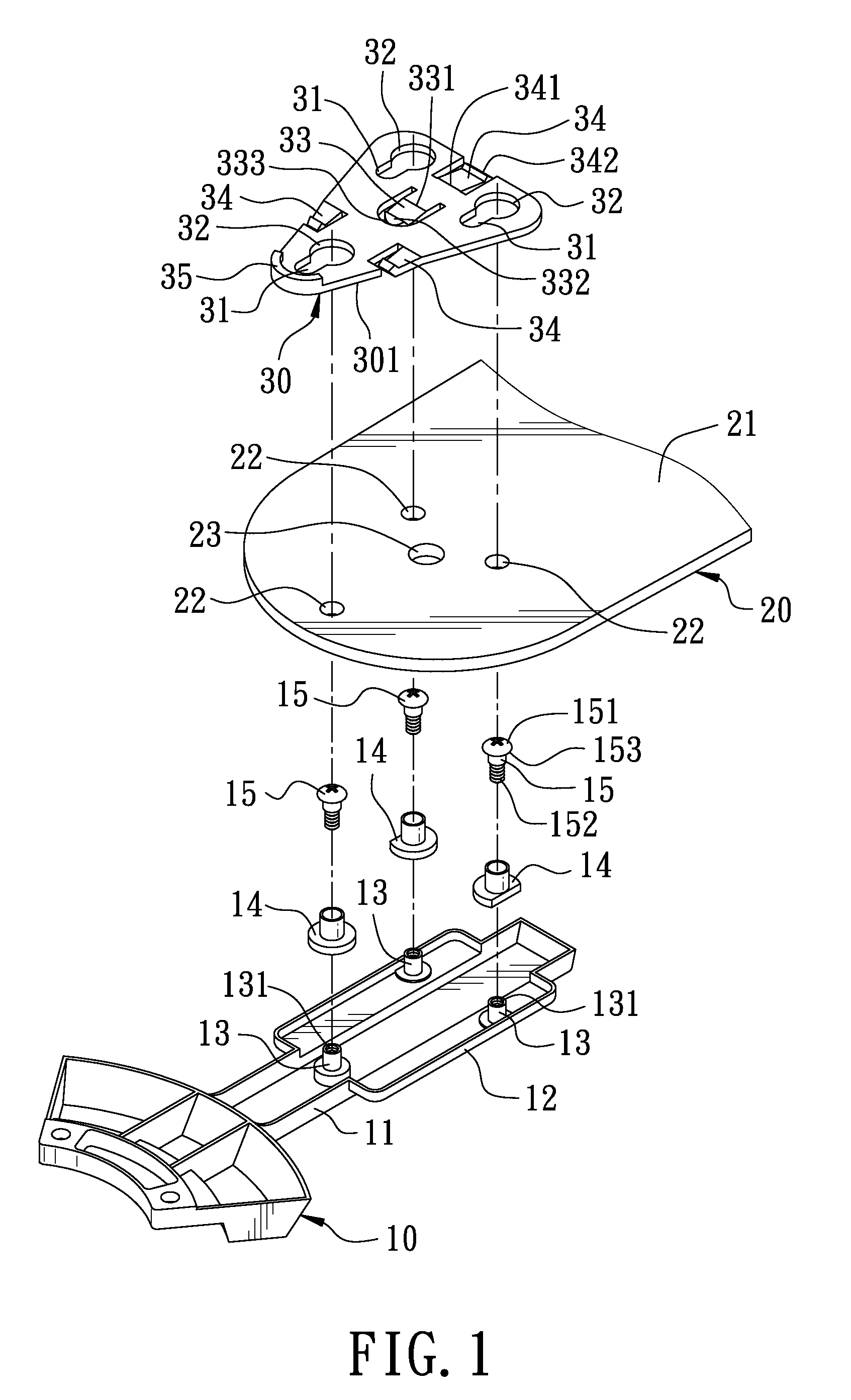
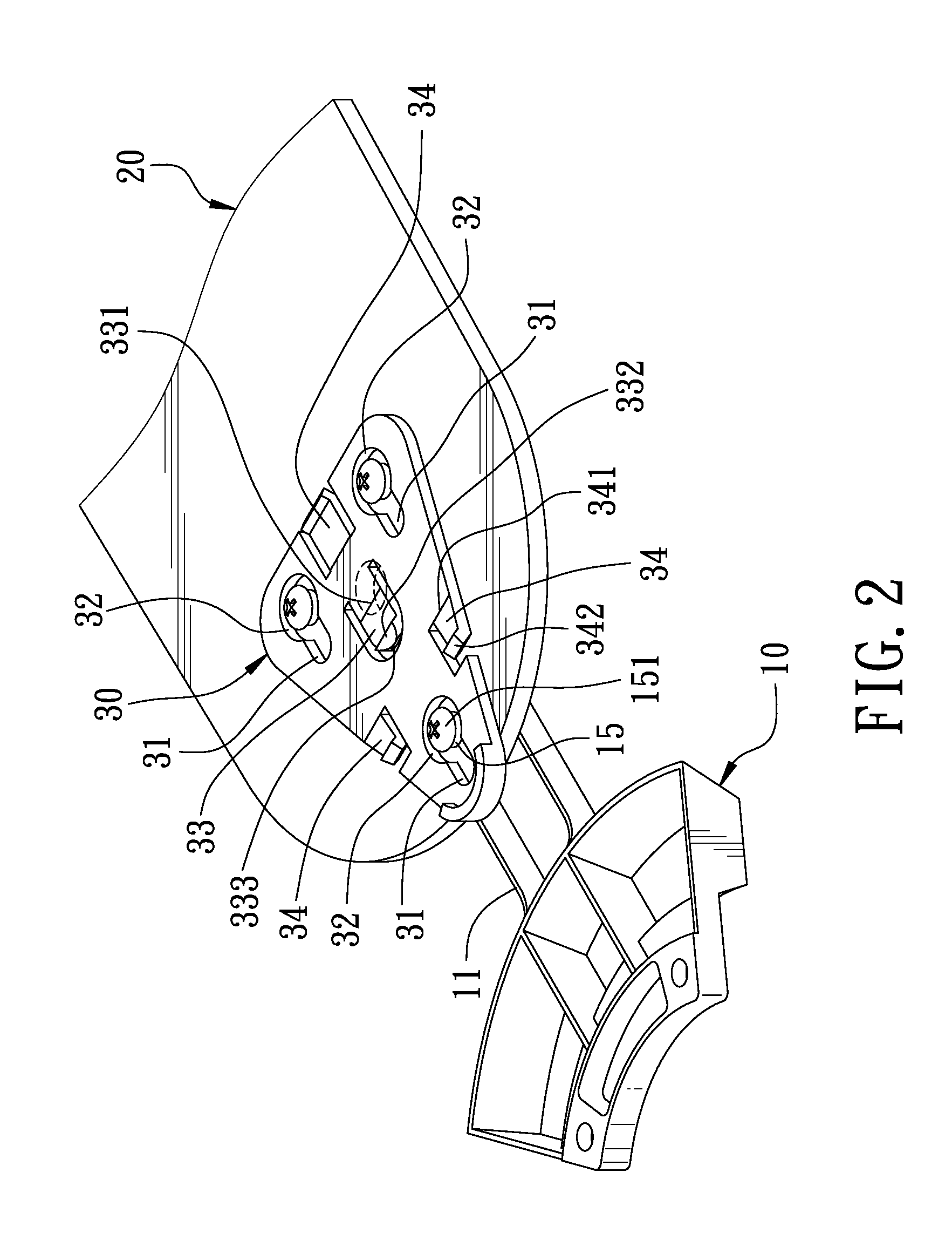
[0014]A first preferred embodiment of a quick assembly blade for a ceiling fan in the present invention, as shown in FIGS. 1, 2 and 3, includes a blade frame 10, a blade 20 and a press board 30 combined together.

[0015]The blade frame 10 has its rear end extended backward and formed with a framework 11 having its rear side expanded to form a pan-shaped body 12 formed integral with three studs 13 extending upward. One of the three studs 13 is positioned at the front end of the pan-shaped body 12, while the other two studs 13 are respectively positioned at the opposite rear ends of the pan-shaped body 12. The three studs 13 are spaced apart and arranged into a triangle in position, and respectively bored with a threaded hole 131 in the center. Further, the three studs 13 are respectively fitted thereon with a bushing 14 shaped as a hollow cylinder made of plastic and respectively secured thereon with a fastener 15 (a bolt), which has its upper end formed with comparatively large round ...


PUM


Abstract

A quick assembly blade for a ceiling fan includes a blade frame, a blade and a press board. The blade frame has at least three studs respectively secured thereon with a fastener to be fitted in the insert holes of the blade and the engage holes of the press board. The engage holes of the press board have their rear ends respectively expanded to form a receiving hole with a comparatively large diameter. The blade is bored with a positioning hole among its insert holes, and the press board is disposed with at least one stopper at a location corresponding to the positioning hole of the blade. Thus, when the press board is assembled on the blade, the engage holes is respectively fixed with the underside of the fasteners, and the stopper is stuck in the positioning hole to prevent the press board from disengaging, thus quickly finishing assembly of the blade.

Description

BACKGROUND OF THE INVENTION[0001]1. Field of the Invention[0002]This invention relates to a ceiling fan, particularly to one whose blades are stable in structure, have integral beauty and can be assembled quickly.[0003]2. Description of the Prior Art[0004]For quickly assembling a blade of a conventional ceiling fan on a blade frame, the blade frame has its disc body secured with three studs, and the blade is bored with three engage holes respectively corresponding to the three studs of the blade frame. An elastic stopper is to be fitted on the studs at the front end of the blade frame, having its rear end protruding upward and formed with a stop member. In assembling, firstly, the blade has its engage holes respectively engaged with an engage portion at the upper end of the studs of the blade frame, and then each elastic stop strip is fitted on each stud with its stop member stopping the front end of the blade. Thus, after assembled on the blade frame, the blade cannot be shifted ho...

Claims


Application Information

Patent Timeline
Patent Type & Authority Applications(United States)
IPC IPC(8): F04D29/34
CPCF04D29/34F04D25/088
Inventor WANG, CLIFF
Owner AIR COOL INDAL
Learn More