
Method and System for Identifying Database Triggers

a database and trigger technology, applied in the field of data processing system, can solve the problems of difficult to achieve software application enhancements needed to accommodate process changes within the enterprise, small space for future enhancement or adjustment, and frustration of the enterpris

Inactive Publication Date: 2009-02-05
INT BUSINESS MASCH CORP
View PDF18 Cites 13 Cited by
  • Summary
  • Abstract
  • Description
  • Claims
  • Application Information

AI Technical Summary

Problems solved by technology

In today's dynamic data processing environment, an enterprise may encounter frustration because software application enhancement needed accommodate process changes within the enterprise is difficult to accomplish without totally redesigning the entire system.
This type of database schema design leaves little room for future enhancement or adjustment.
This type of software application tends to provide only limited application enhancement ability for certain application actions and cannot cover all possible end user scenarios that might occur in real life.
This second approach usually is very time consuming and relies heavily on the developer's database skills and understanding of database table relationships.
Consequently, using this approach, if a developer does not posses the required database expertise to design and develop enterprise logics based on triggers that are previously not available or otherwise costly to discover, application enhancement is hampered.
Both of these options create large expenditures for the enterprise and cause decreased enterprise productivity due to delayed system modifications.

Method used


Image

  • Method and System for Identifying Database Triggers
  • Method and System for Identifying Database Triggers
  • Method and System for Identifying Database Triggers

Examples


Embodiment Construction

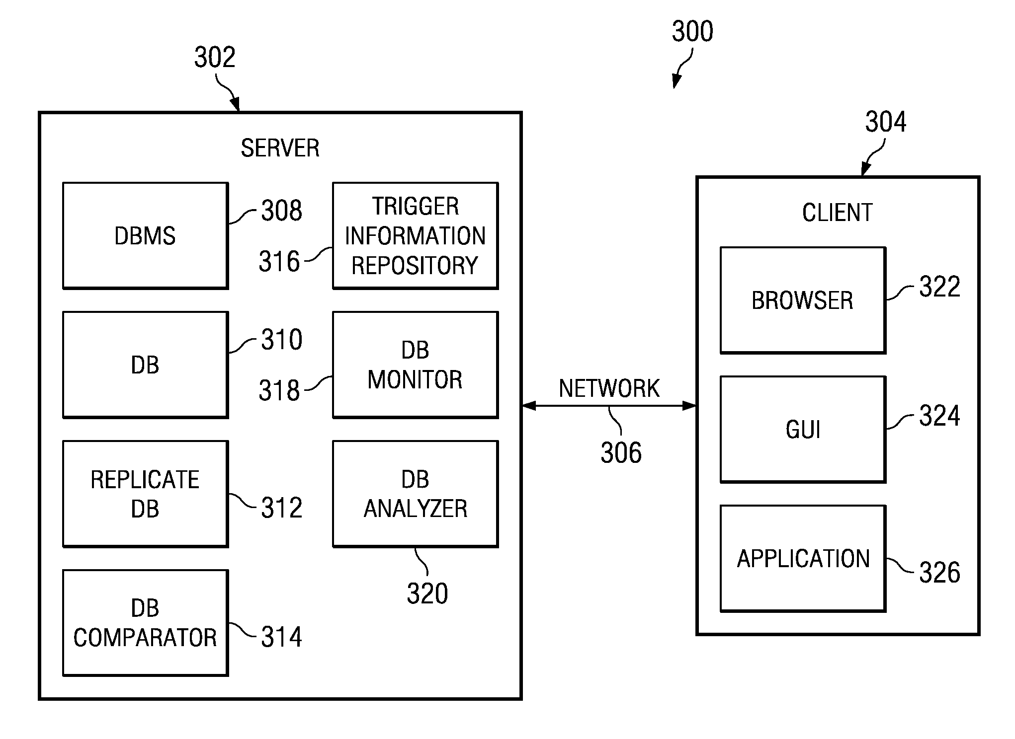
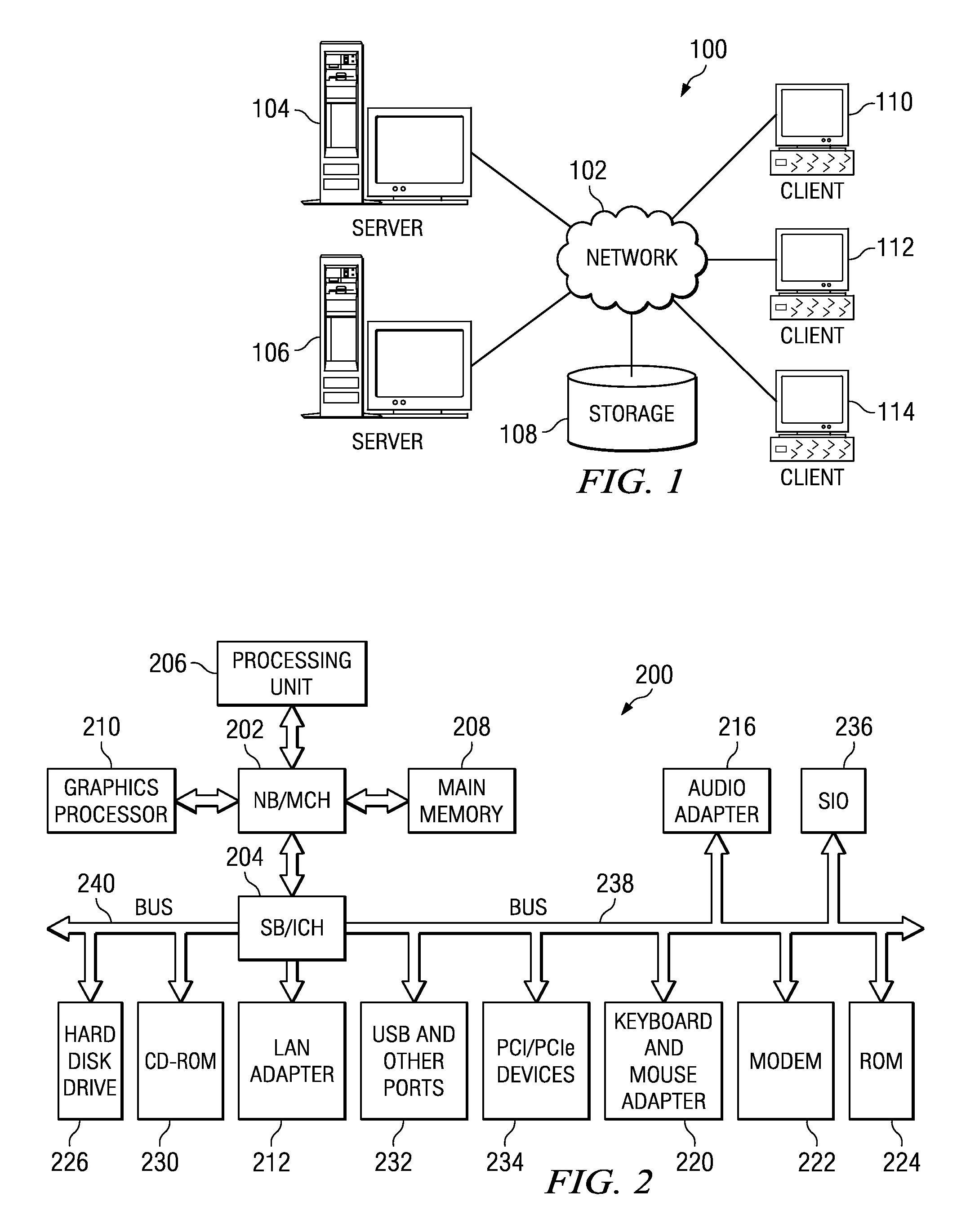
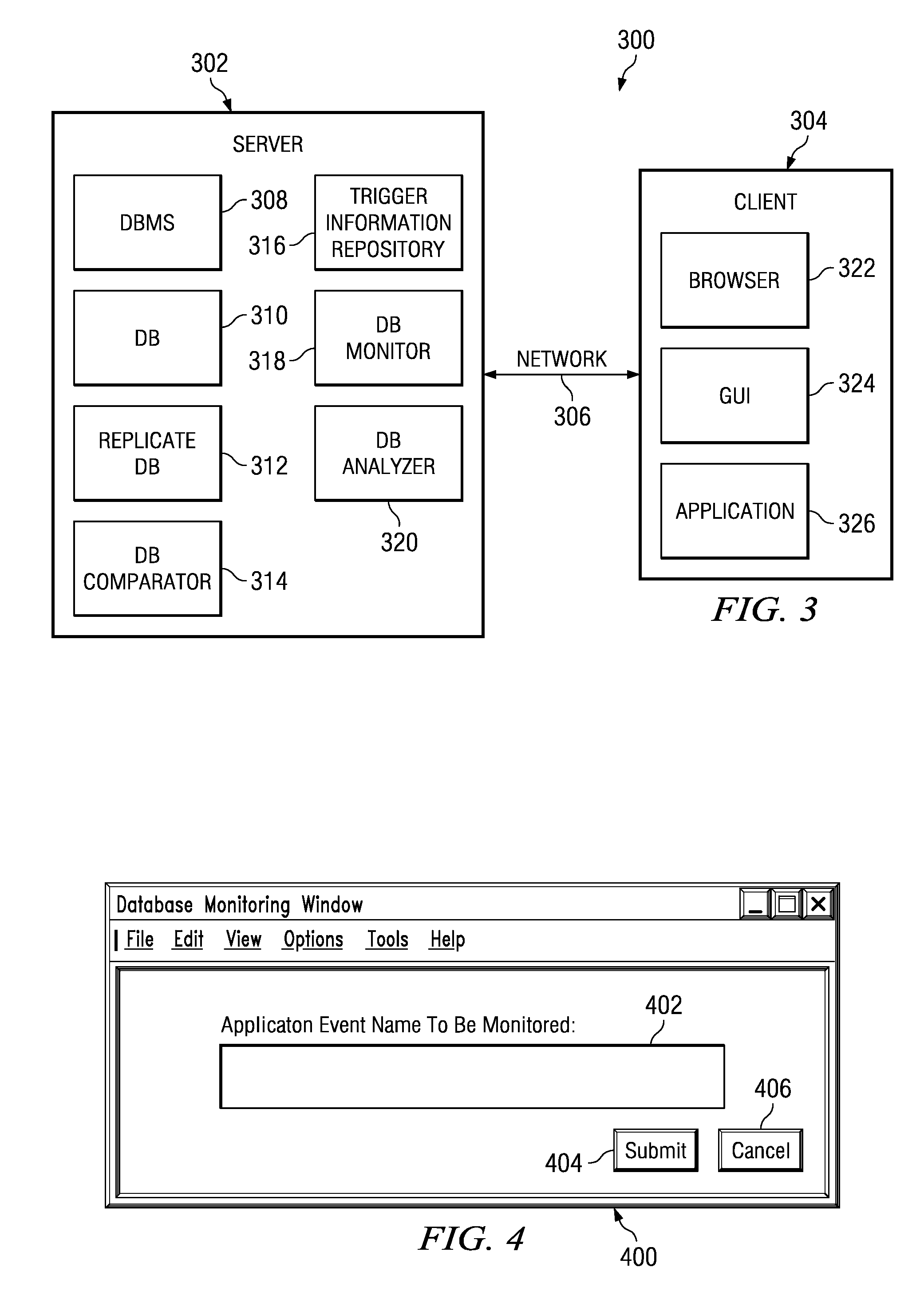
[0022]With reference now to the figures and in particular with reference to FIGS. 1-2, exemplary diagrams of data processing environments are provided in which embodiments of the present invention may be implemented. It should be appreciated that FIGS. 1-2 are only exemplary and are not intended to assert or imply any limitation with regard to the environments in which aspects or embodiments of the present invention may be implemented. Many modifications to the depicted environments may be made without departing from the spirit and scope of the present invention.

[0023]With reference now to the figures, FIG. 1 depicts a pictorial representation of a network of data processing systems in which aspects of the present invention may be implemented. Network data processing system 100 is a network of computers in which embodiments of the present invention may be implemented. Network data processing system 100 contains network 102, which is the medium used to provide communications links be...


PUM


Abstract

A system to identify database triggers in a data processing system. A request is received to create a database monitor for a specific application event and in response to receiving the request to create the database monitor, the database monitor is created. Then, a request is received to monitor the specific application event within a database and in response to receiving the request to monitor the specific application event, a replicate database of the database is created. Subsequently, the database is compared to the replicate database after the specific application event occurs to identify changes in the database associated with the specific application event. A best candidate is identified for a database trigger based upon the identified changes in the database associated with the specific application event.

Description

BACKGROUND OF THE INVENTION[0001]1. Field of the Invention[0002]The present invention relates generally to an improved data processing system. More specifically, the present invention is directed to a computer implemented method, apparatus, and computer useable program code to identify database triggers.[0003]2. Description of the Related Art[0004]In today's dynamic data processing environment, an enterprise may encounter frustration because software application enhancement needed accommodate process changes within the enterprise is difficult to accomplish without totally redesigning the entire system. Often system integrators and software vendors design systems based upon current enterprise processes. Consequently, the systems tend to be rigid. This is particularly true for database application systems where the original design of the database schema dictates what actions the application can perform. This type of database schema design leaves little room for future enhancement or a...

Claims


Application Information

Patent Timeline
Patent Type & Authority Applications(United States)
IPC IPC(8): G06F17/30
CPCG06F17/30312Y10S707/99943Y10S707/99944Y10S707/99953G06F16/22
Inventor MEDICKE, JOHN A.RUSSELL, FENG-WEI CHENSMITH, MICHAEL WILLIAMTAN, RAY ZHONG
Owner INT BUSINESS MASCH CORP
Learn More