Cryopanel and Cryopump Using the Cryopanel

a technology of cryopanels and cryopumps, which is applied in the direction of positive displacement liquid engines, lighting and heating apparatus, separation processes, etc., can solve the problems of limited discharge velocity and limited discharge velocity

Inactive Publication Date: 2009-02-12
SUMITOMO HEAVY IND LTD
View PDF11 Cites 15 Cited by
  • Summary
  • Abstract
  • Description
  • Claims
  • Application Information

AI Technical Summary

Benefits of technology

[0013]Accordingly, embodiments of the present invention may provide a novel and useful cryopanel and cryopump using the cryopanel solving one or more of the problems discussed above.
[0014]More specifically, the embodiments of the present invention may provide a cryopanel whereby discharge velocity and solidifying and absorption efficiencies are improved and may also provide a cryopump using the cryopanel.
[0035]According to the embodiments of the present invention, it is possible to provide a cryopanel whereby discharge velocity and solidifying and absorption efficiencies are improved and to also provide a cryopump using the cryopanel.

Problems solved by technology

Therefore, under this structure, the discharge velocity is limited.

Method used


Image

  • Cryopanel and Cryopump Using the Cryopanel
  • Cryopanel and Cryopump Using the Cryopanel
  • Cryopanel and Cryopump Using the Cryopanel

Examples


first modified example

[0081]FIG. 3 is a view of a cryopanel of a first modified example of the embodiment of the present invention (FIG. 3(a) is a front view and FIG. 3(b) is a plan view).

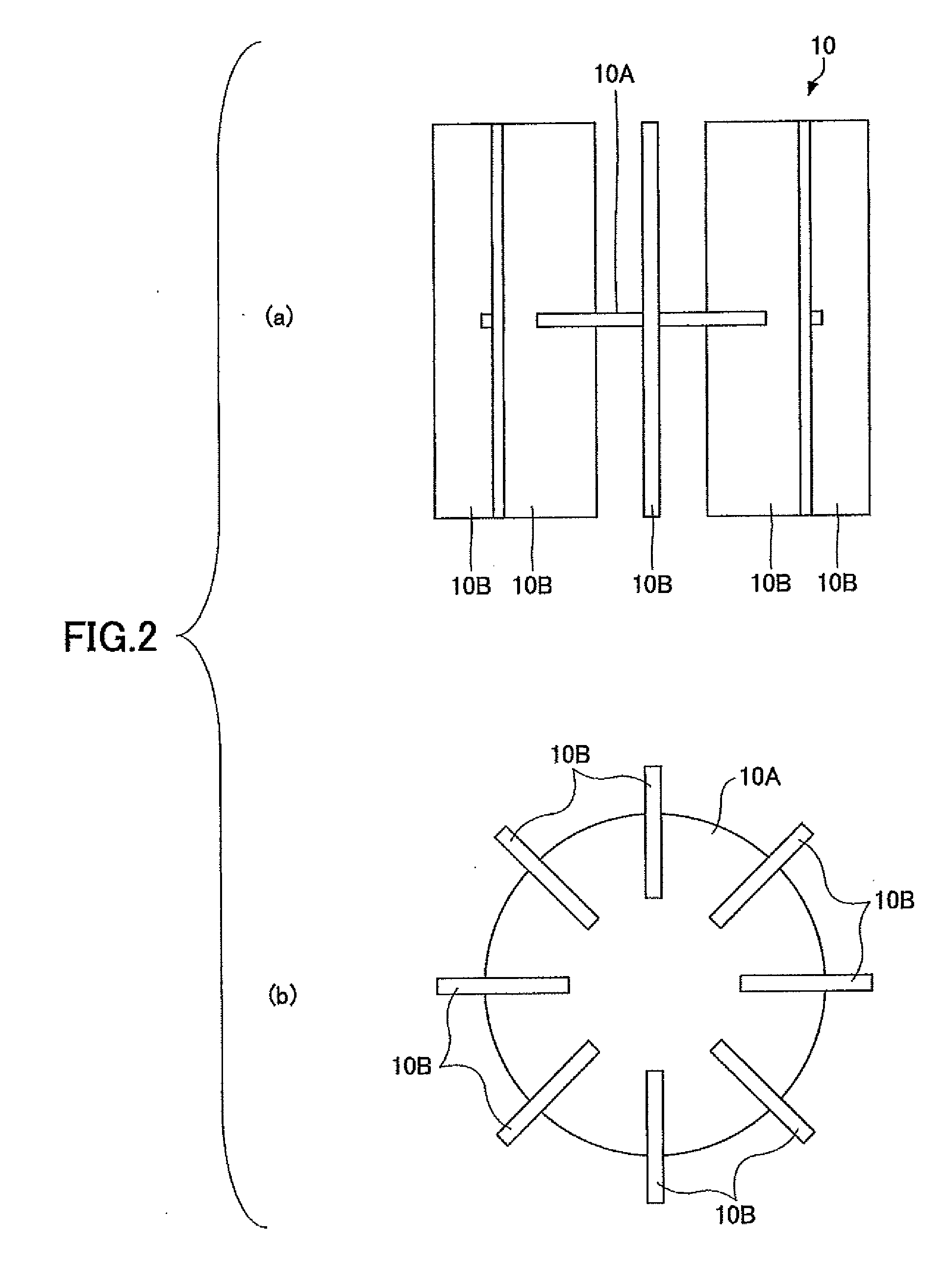
[0082]In a cryopanel 20, unlike the cryopanel 10 shown in FIG. 2, end parts in diameter directions of plate-shaped panels 20B are situated in the same position as (diameter direction positions of) the external circumference of the disk-shaped panel 20A. The diameter of the disk-shaped panel 20A is the same as that of the disk-shaped panel 10A shown in FIG. 2. The plate-shaped panels 20B have the same lengths from the disk-shaped panel 20A to the upstream side and the downstream side of the gas flow-in.

[0083]According to the above-mentioned cryopanel 20, it is possible to improve the discharge velocity. In particular, since the surface area of the plate-shaped panels 203 where the active layers are formed is increased, it is possible to improve the absorption rate of hydrogen, neon, helium, and the like. Hydrogen, neon, ...

second modified example

[0085]FIG. 4 is a view of a cryopanel of a second modified example of the embodiment of the present invention (FIG. 4(a) is a plan view and FIG. 4(b) is a front view).

[0086]In a cryopanel 30, unlike the cryopanel 10 shown in FIG. 2, end parts in diameter directions of the plate-shape panels 30B are situated in the same position as (diameter direction positions of) the external circumference of the disk-shaped panel 30A. In addition, the plate-shaped panels 30B are connected to each other at the center in a diameter direction of the disk-shaped panel 30A.

[0087]Furthermore, the diameter of the disk-shaped panel 30A is the same as that of the disk-shaped panel 10A shown in FIG. 2. The plate-shaped panels 30B extend from the disk-shaped panel 30A in only the upstream direction of the gas flow-in.

[0088]According to the above-mentioned cryopanel 30, the plate-shaped panels 30B where the active layers are formed are provided at the upstream side of the disk-shaped panel 30A. Hence, compare...

third modified example

[0090]FIG. 5 is a view of a cryopanel of a third modified example of the embodiment of the present invention (FIG. 5(a) is a front view and FIG. 5(b) is a plan view).

[0091]Plate-shaped panels 40B of the cryopanel 40, unlike the plate-shaped panels 30B of the cryopanel 30, are not provided in the vicinity of the center in the diameter direction of a disk-shaped panel 40A. The cryopanel 40 is formed by connecting two disk-shaped panels 40A. Eight plate-shaped panels 40B are formed on one surface of each disk-shaped panel 40A.

[0092]By this connection of two disk-shaped panels 40A, it is possible to obtain the cryopanel 40 having the same configuration as the cryopanel 20 shown in FIG. 3.

[0093]According to the above-mentioned cryopanel 40, it is possible to improve the discharge velocity. In particular, since the surface area of the plate-shaped panel 40B where the active layer is formed is increased, it is possible to improve the absorption rate of hydrogen, neon, helium, and the like....


PUM

PropertyMeasurementUnit
temperatureaaaaaaaaaa

Abstract

A cryopanel used for a cryopump, the cryopump including a vacuum chamber having a gas flow-in opening; a stage provided in the vacuum chamber; and a cryocooler configured to cool the stage, the cryopump being configured to solidify or absorb a molecule flowing from the gas flow-in opening into the vacuum chamber, the cryopanel includes a first panel held and cooled by the stage, the first panel having a surface facing toward the gas flow-in opening; and a second panel held by the first panel and extending from the first panel in an upstream direction of a gas flow-in, the second panel having a surface where an absorption material layer is formed.

Description

BACKGROUND OF THE INVENTION[0001]1. Field of the Invention[0002]The present invention generally relates to cryopanels and cryopumps using the cryopanels.[0003]2. Description of the Related Art[0004]In semiconductor manufacturing apparatuses, cryopumps have been used for realizing high vacuum states. The cryopump realizes the high vacuum state by cooling a cryopanel situated in a vacuum chamber and solidifying or absorbing molecules.[0005]It is normal practice that the cryopanel is connected to a stage of a cryocooler. The cryopanel includes a disk-shaped panel and plural plate-shaped panels. The front surface of the disk-shaped panel is provided horizontally and facing in an upstream direction in a gas flow-in. Plural plate-shape panels are provided on the rear surface side of the disk-shaped panel and extend in a direction downstream in the gas flow-in.[0006]Gas in a process chamber flows in from an upper part opening of the vacuum chamber. Hydro-molecules are solidified mainly by ...

Claims


Application Information

Patent Timeline
Patent Type & Authority Applications(United States)
IPC IPC(8): F04B37/08B01D8/00
CPCF04B37/08
Inventor TSUYUKI, RYOSUKE
Owner SUMITOMO HEAVY IND LTD
Why Eureka
Try Eureka