Memo Pad Structure

Inactive Publication Date: 2009-02-12
KUDOS FINDER TRADING
View PDF10 Cites 10 Cited by
  • Summary
  • Abstract
  • Description
  • Claims
  • Application Information

AI Technical Summary

Benefits of technology

[0007]The objective for the invention is to provide a memo pad structure that is simple, convenient and

Problems solved by technology

However, a product with simple function and no attractive features tends to be replaced and out of the market.
Although some people attempt to attract consumers' attention and increase mark

Method used


Image

  • Memo Pad Structure
  • Memo Pad Structure
  • Memo Pad Structure

Examples


Example

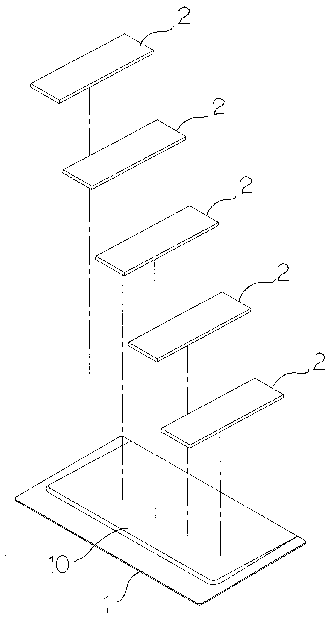
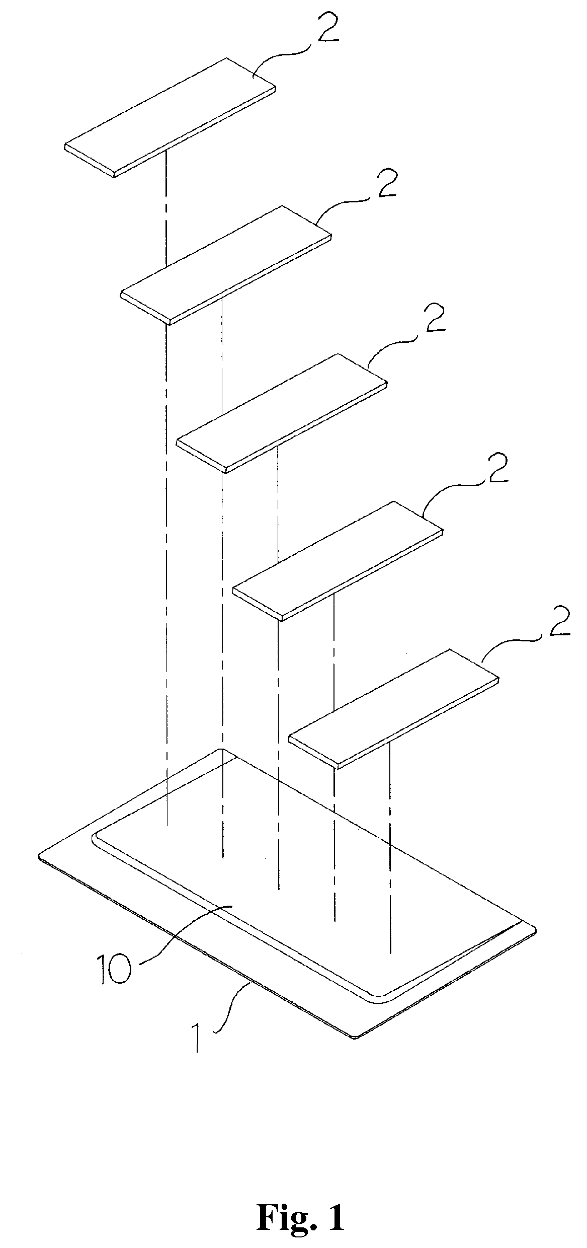
[0014]Please refer to FIG. 1 for a preferred embodiment for the new memo pad structure, which includes a fixation base (1) and several memo pad stacks (2) attached on it.

[0015]The fixation base (1) is made of hard plastics in thin flat sheet which surface is an ergonomic slope (10) that rises from one side to the other.

[0016]A plurality of memo pad stacks (2) are lined up on the slope (10) of the fixation base (1). Their one end sticks out of the slope (10) on the high side to facilitate peeling off a single pad. Each memo pad stack (2) is composed of a plurality of single memo pads (20) partially bonded together.

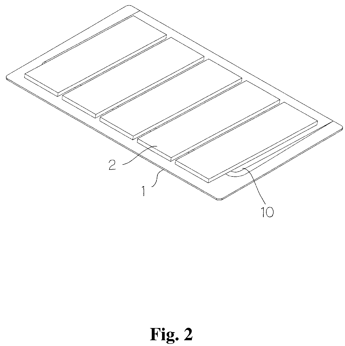
[0017]Such an integrated, lightweight and convenient memo pad structure is shown in FIG. 2.

[0018]Please refer to FIG. 3. When the above memo pad structure is in use, the user picks one memo pad stack (2) and peels off one single memo pad (20). The user's hand lifts up one memo pad stack (2) and peels off the outermost single memo pad (20). The pad can be attached to a desig...


PUM


Abstract

The invention is related to a new memo pad structure that is lightweight, portable and convenient. Its fixation base has an ergonomic rising slope, on which there are a plurality of memo pad stacks. Each memo pad stack is composed of a plurality of single memo pads adhesively bonded together. The memo pad stacks are lined up on the slope and stick out of the high side of the slope to facilitate the peeling. Besides, the memo pad stacks can be made in different colors or with different surface patterns for the purposes of identification, aesthetics and classification.

Description

BACKGROUND OF THE INVENTION [0001]1. Field of the Invention[0002]The invention is related to a new memo pad structure. Especially it refers to a light, portable and agronomic memo pad structure. Further, the invention provides different colors or local patterns to increase aesthetic and visual effect.[0003]2. Description of the Prior Art[0004]It is common for people to use memo pads in workplace, for emergency contact, messages, reply and reminder et al. Usually memo pads are a stack of a plurality of paper sheets in a certain size. Their back has self-stick adhesive in partial area. The pads are placed into a rectangle fixation base. Thus, the user can peel the pad off, put texts on it, and post it in a place that can be easily noticed. Or the user can stick the pad to the edge of a file folder to note the document category on it. The memo pads provide multiple application functions.[0005]The traditional memo pads as described above and their fixation base does not seem to have a b...

Claims


Application Information

Patent Timeline
IPC IPC(8): B42D17/00
CPCB42D5/005
Inventor JOUR, DAVID C.T.
Owner KUDOS FINDER TRADING
Why Eureka
Try Eureka