
Image pickup apparatus and image pickup method

a technology of image pickup and image, which is applied in the direction of picture signal generators, still video cameras, television systems, etc., can solve the problems of inconvenient classification information, inability to consider the proper properties according to the content of images,

Active Publication Date: 2009-02-12
CANON KK
View PDF12 Cites 20 Cited by
  • Summary
  • Abstract
  • Description
  • Claims
  • Application Information

AI Technical Summary

Benefits of technology

[0011]The present invention also provides a technique for judiciously editing photographing information provided to an image at the time of image editing. The present invention also provides a technique for allowing photographing information to be suitably displayed at the time of image reproduction.

Problems solved by technology

However, in the above mentioned techniques, because an image is viewed by use of a history of editing (operation), provision of proper properties according to the content of an image is not considered.
For example, in the case of an image of people captured in a shooting mode suited for capturing images of people, the provision of classification information regarding people to the image raises no problem at this time, but such people classification information is probably inconvenient when a portion other than people is cut out from the image by cropping.

Method used


Image

  • Image pickup apparatus and image pickup method
  • Image pickup apparatus and image pickup method
  • Image pickup apparatus and image pickup method

Examples


first embodiment

Structure of Digital Camera

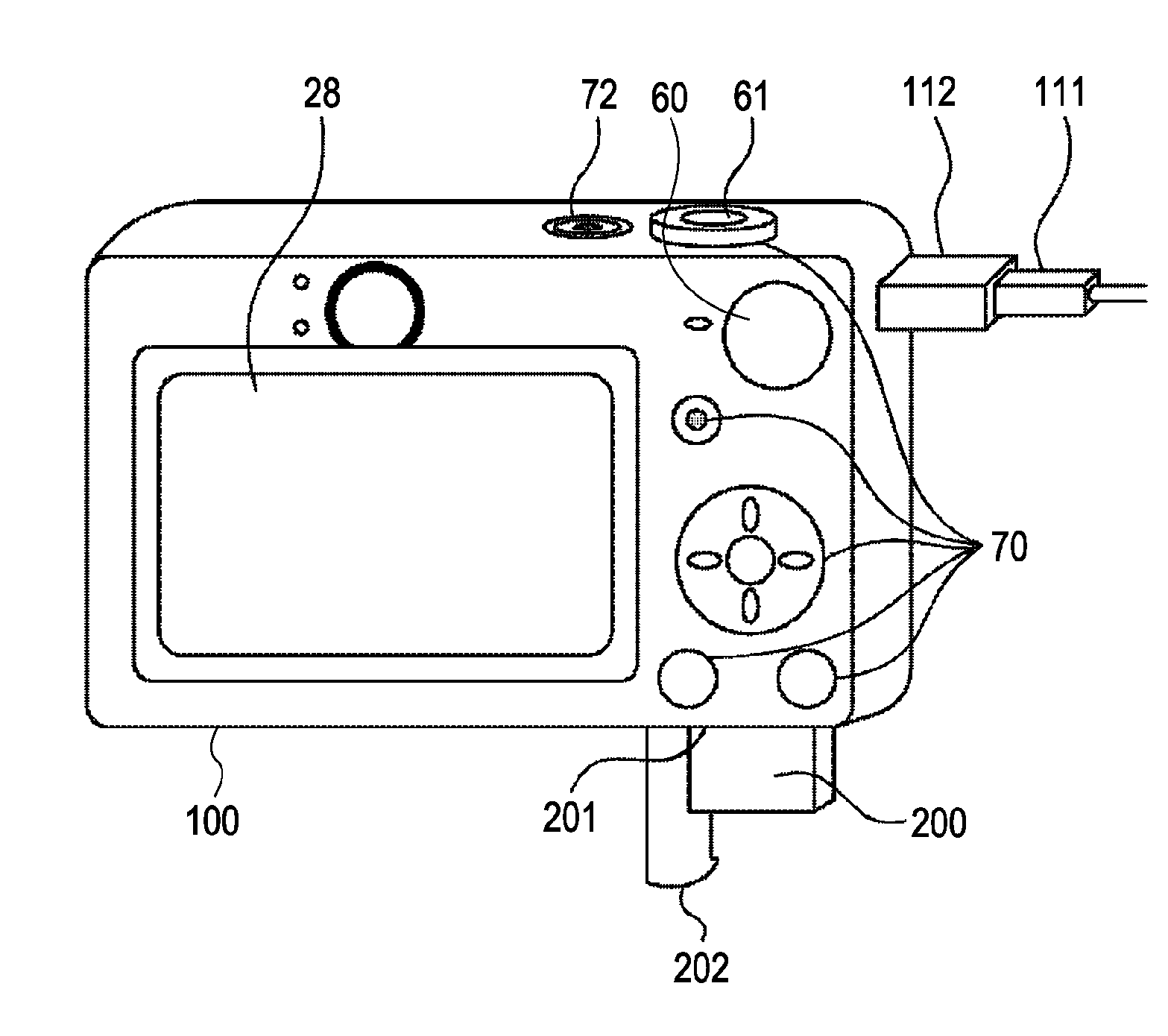
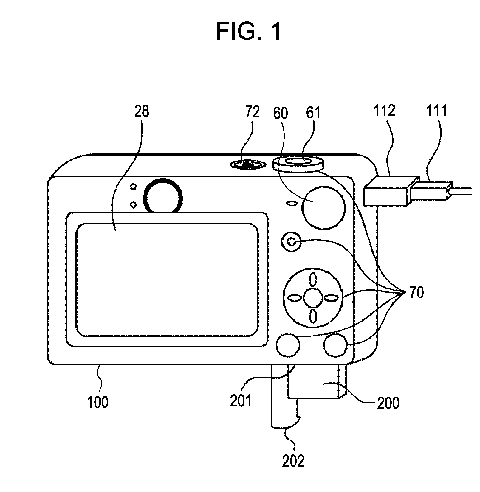
[0040]FIG. 1 is an external view of a digital camera 100 according to an embodiment of the present invention. An image display portion 28 displays an image and various kinds of information. A power switch 72 is used to switch the power between on and off states. Reference numeral 61 indicates a shutter release button. A mode selector 60 is used to switch among various modes for use in the digital camera 100. Specifically, the mode is switchable among still-image recording mode, movie recording mode, and reproducing mode, for example.

[0041]An operation portion 70 is configured to receive various kings of operation from a user. The operation portion 70 includes various kinds of button, which are illustrated in FIG. 1, and an operation member, such as a touch panel on the screen of the image display portion 28. Examples of the various buttons of the operation portion 70 include an Erase button, a Menu button, a Set button, four direction buttons (up, down, ri...

second embodiment

[0221]A second embodiment is described below with reference to the accompanying drawings.

[0222]One major point of the differences to the first embodiment is that, in the present embodiment, capturing information, such as focusing frame and capturing date, is provided to an image in addition to classification information, whereas in the first embodiment classification information is provided to an image. The following description focuses on this point.

[0223]The detailed description of parts shared by the first embodiment, such as the structure of the digital camera, capturing, recording, reproducing, processing in each mode, and the structure of a file, is omitted.

Header Generation

[0224]Another example of the header generation process in step S706 of FIG. 7 will now be described with reference to FIG. 24.

[0225]In step S2401, the system controller 50 obtains the set value for ON or OFF of the setting of automatically providing classification information specified in step S405 of FIG. ...


PUM


Abstract

Disclosed is a technique for allowing proper classification information to be provided to an edited image. When it is determined that the editing is cropping, a system controller cuts a decompressed image down to a desired size using an image processor and performs face detection on a crop image. The system controller generates a header for image data of an edited image. When the setting of automatically providing classification information is “ON”, classification information is automatically provided based on the detected face information.

Description

BACKGROUND OF THE INVENTION[0001]1. Field of the Invention[0002]The present invention relates to an image pickup apparatus capable of providing an image with classification information and to a method therefor.[0003]2. Description of the Related Art[0004]With the widespread use of digital cameras, storing data of an image captured by a digital camera and image data captured from a personal computer (hereinafter referred to as a “PC”) on various types of recording media by the digital camera and the PC has become popular.[0005]Image data stored on a recording medium is reproduced by an image reproducing apparatus, such as a digital camera, a PC, or a printer, in order to be viewed, edited, organized, or other reasons.[0006]There are a digital camera, a PC, and a printer that can provide images with properties for enabling efficient image retrieval and that allows a user to retrieve an image using the properties as a retrieval key.[0007]There is a digital camera that can display an in...

Claims


Application Information

Patent Timeline
Patent Type & Authority Applications(United States)
IPC IPC(8): H04N5/225
CPCG06F17/30247H04N2201/3277H04N1/32128H04N5/23212H04N5/23219H04N5/23245H04N5/2354H04N5/3454H04N5/772H04N5/781H04N5/907H04N9/8042H04N9/8227H04N2101/00H04N2201/3214H04N2201/3215H04N2201/3226H04N2201/325H04N1/00167G06F16/583H04N2201/3251H04N23/611H04N23/667H04N25/443H04N23/74
Inventor NAKASE, YUICHIINAGAKI, ATSUSHISANNO, MASATOIKEDA, HITOSHINIWA, CHIYUMIWATANABE, HITOSHI
Owner CANON KK
Learn More