Temperature-measuring device for a respiration humidifier

a technology of temperature measurement and humidifier, which is applied in the direction of heat measurement, optical radiation measurement, instruments, etc., can solve the problems of hygienic risks, complicated handling of prior-art design or system, and higher costs in the case of disposable flexible tube systems

Active Publication Date: 2009-02-12
DRAGERWERK AG
View PDF13 Cites 18 Cited by
  • Summary
  • Abstract
  • Description
  • Claims
  • Application Information

AI Technical Summary

Benefits of technology

[0004]The object of the present invention is to propose a temperature-measuring device especially for a respiration humidifier, which is improved in respect to the handling and reliability of the measurement and can be used for both disposable and reusable systems.
[0005]According to one embodiment, a temperature-measuring device for a respiration humidifier may be provided with at least one flow channel for a breathing gas. The device may comprise a hollow body having a closed end surface. The hollow body may extend into the at least one flow channel for assuming a temperature in the at least one flow channel. The hollow body may have an inner surface. An infrared detector may face in a direction of the inner surface of the hollow body for the contactless detection of the temperature of the hollow body. An essential advantage of the contactless temperature-measuring means being proposed for respiration humidifiers consists of the physical uncoupling of the temperature sensor system proper from the temperature measurement site, so that the drawbacks experienced hitherto in the case of the prior-art solutions are eliminated.

Problems solved by technology

There remains a hygienic risk if the procedure is not carried out carefully.
The handling of this prior-art design or system is complicated.
As an alternative, the temperature sensor may be integrated in the flexible breathing tube system as a fixed component of this system, which leads to higher costs in case of disposable flexible tube systems if the temperature sensor is disposed of together with the flexible tube system after use.
Cables must be additionally led from the respiration humidifier to the flexible tube system in case of flexible tube systems used several times, which may lead to additional costs, and due to the repeated cleaning, disinfection or sterilization operations, to limited reliability of operation of the cables and electric plug connections.

Method used


Image

  • Temperature-measuring device for a respiration humidifier
  • Temperature-measuring device for a respiration humidifier
  • Temperature-measuring device for a respiration humidifier

Examples


Embodiment Construction

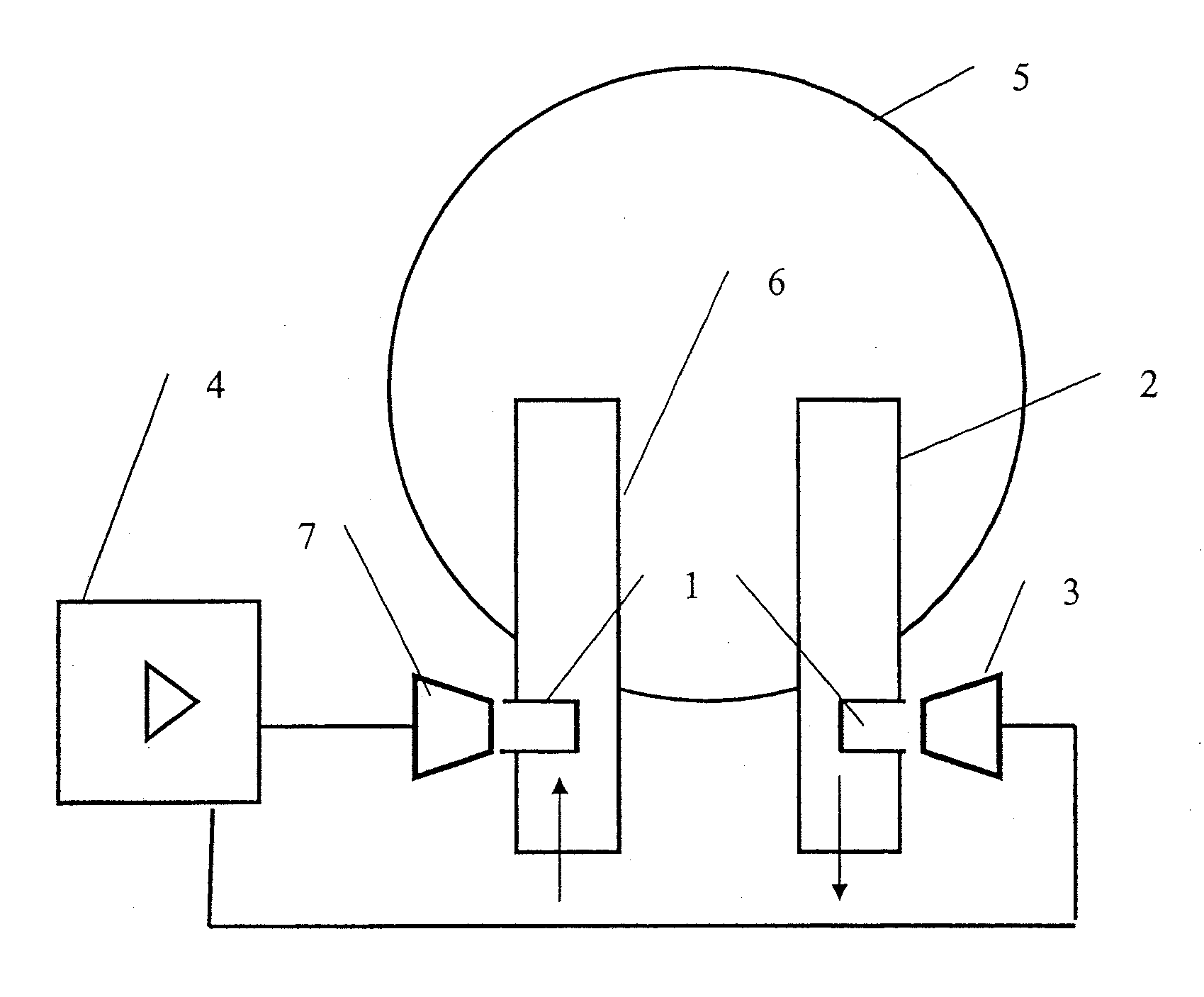
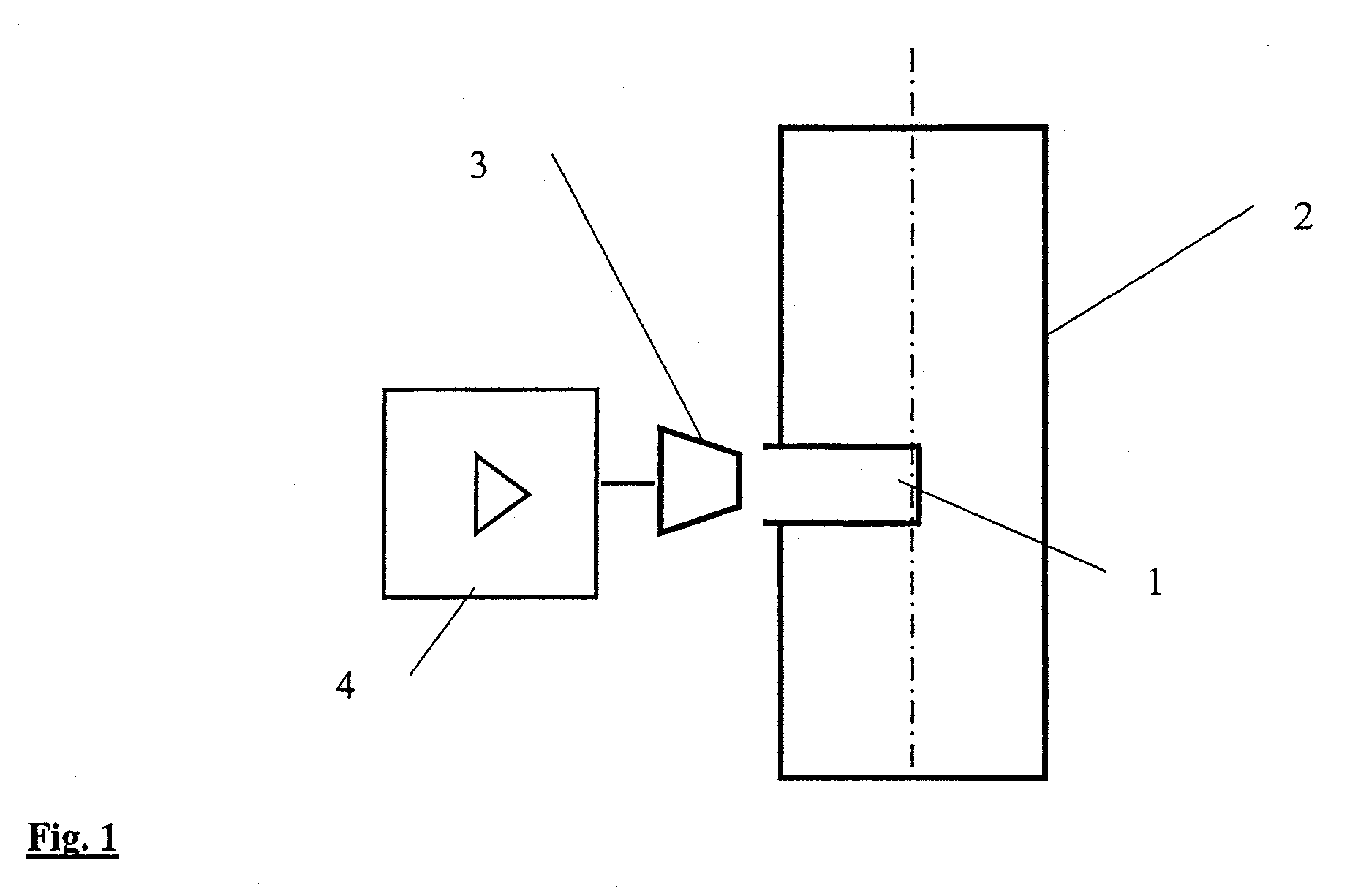
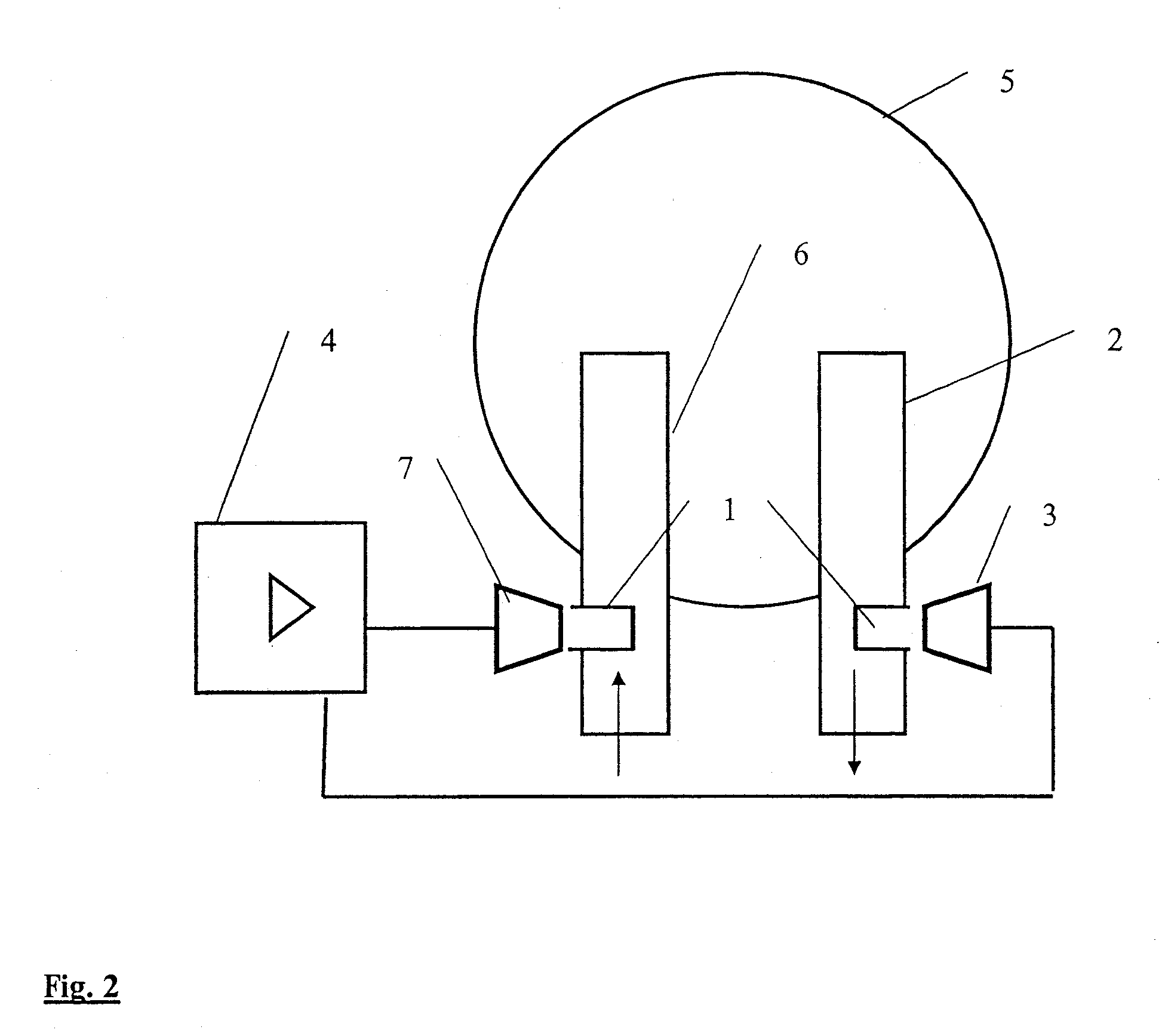
[0029]Referring to the drawings in particular, FIG. 1, a flow channel 2 leading out of, for example, a respiration humidifier, is provided with a hollow body 1, which extends or protrudes into the central longitudinal axis of the flow channel 2 and is especially cylindrical.

[0030]The hollow body 1 is used to assume the temperature of the breathing gases flowing in the flow channel 2. The temperature in the hollow body 1 and thus the corresponding temperature of the breathing gas flow is detected with the correspondingly oriented infrared detector 3 from the outside and in a physically uncoupled manner.

[0031]The surface of the material of the hollow body 1 is selected to be such that the emission coefficient for heat radiation is as close to 1.0 as possible. As an alternative, the surface of the hollow body 1 is blackened.

[0032]The hollow body 1 assumes an average temperature during the measurement. The heat dissipation to the environment or to the flow channel 2 is minimized via the...


PUM

PropertyMeasurementUnit
temperatureaaaaaaaaaa
flexibleaaaaaaaaaa

Abstract

A contactless temperature-measuring device especially for a respiration humidifier with a flow channel for breathing gas, which is improved in respect to handling and reliability of measurement. The device includes: a hollow body (1), which is closed towards the flow channel (2, 6), extends into the flow channel (2, 6) for assuming the temperature in the flow channel (2, 6); and an infrared detector (3, 7) is directed toward the inner surface of the hollow body (1) extending into the flow channel (2, 6) for the contactless detection of the temperature of the hollow body (1).

Description

CROSS REFERENCE TO RELATED APPLICATIONS[0001]This application claims the benefit of priority under 35 U.S.C. §119 of German Patent Application DE 10 2007 037 955.4 filed Aug. 11, 2007, the entire contents of which are incorporated herein by reference.FIELD OF THE INVENTION[0002]The present invention pertains to a temperature-measuring device for a respiration humidifier.BACKGROUND OF THE INVENTION[0003]The breathing gas temperature at the outlet of the mixing chamber with the humidified breathing gas is measured in prior-art respiration humidifiers by means of a temperature-dependent resistor element, and the heat output of the water reservoir is regulated accordingly. In disposable flexible breathing tube systems, a reusable temperature sensor, which is connected by a cable to the humidifier proper having a heating means, is plugged for this purpose into the flexible tube. To avoid cross infections, this reusable temperature sensor must be cleaned and sterilized or disinfected afte...

Claims


Application Information

Patent Timeline
Patent Type & Authority Applications(United States)
IPC IPC(8): G01K13/00
CPCA61M16/0816A61M16/16A61M2205/3368A61M16/109G01J5/08G01J5/0887G01J5/0014
Inventor KOCH, JOCHIM
Owner DRAGERWERK AG
Why Eureka
Try Eureka