Terminal positioning method, terminal positioning system, positioning server, and program

a terminal positioning system and positioning server technology, applied in the direction of positioning, location information based service, instruments, etc., can solve the problems of failure of rf-id from which information cannot be read, and the inability to perform positioning

Inactive Publication Date: 2009-02-12
NEC CORP
View PDF5 Cites 53 Cited by
  • Summary
  • Abstract
  • Description
  • Claims
  • Application Information

AI Technical Summary

Benefits of technology

[0019]According to the present invention, in the case of providing a plurality of positioning systems and specifying the position of a terminal, failure detection can be performed without directly detecting a failed positioning system. In particular, also in a large-scale datum-point positioning system having a large number of transmitters for specifying the position of a terminal, which are not connected to a wired network, failure of a transmitter can be detected easily.

Problems solved by technology

In the case of the datum-point positioning, when a transmitter fails for some reason and the ID number cannot be transmitted, the positioning cannot be performed.
An RF-ID from which information cannot be read is regarded as a failed one.

Method used


Image

  • Terminal positioning method, terminal positioning system, positioning server, and program
  • Terminal positioning method, terminal positioning system, positioning server, and program
  • Terminal positioning method, terminal positioning system, positioning server, and program

Examples


first concrete embodiment

[0089]A first concrete embodiment of the present invention will now be described in detail with reference to the drawings.

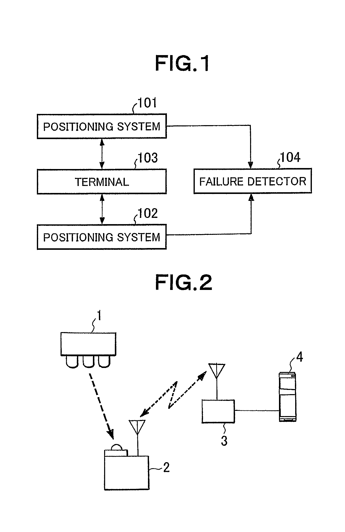
[0090]FIG. 2 is a diagram showing a general configuration of a terminal positioning system of the first concrete embodiment of the invention.

[0091]A positioning system of the concrete embodiment is constructed by the infrared ray transmitter 1, the wireless base station 2, a terminal 3, and the positioning server 4. In place of the infrared ray transmitter, a transmitter that sends an RF-ID and the like may be used.

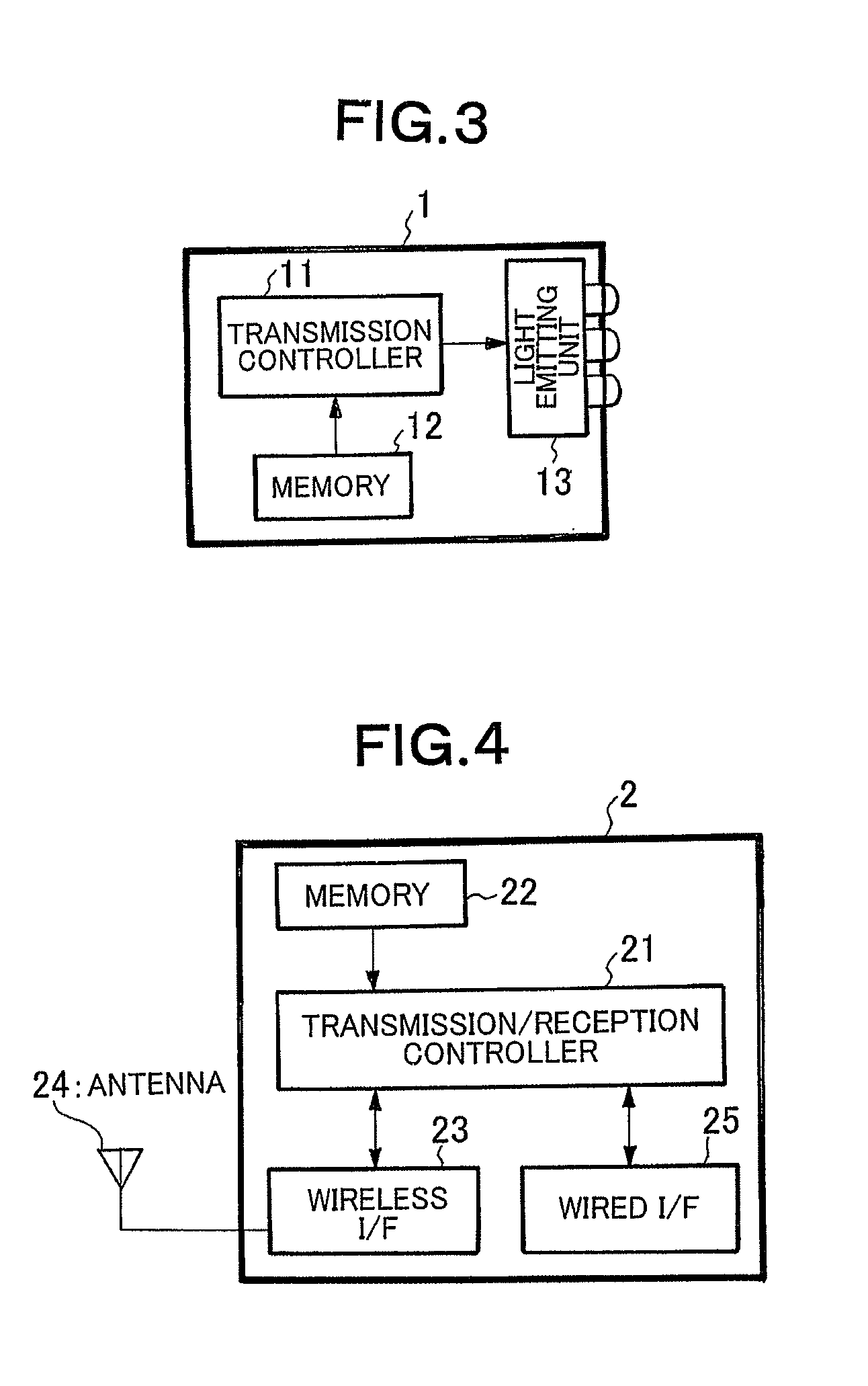
[0092]FIG. 3 is a diagram showing the configuration of the infrared ray transmitter 1.

[0093]The infrared ray transmitter 1 is constructed by a transmission controller 11, a memory 12, and a light emitting unit 13. In the memory 12, the light emission intervals, the number of light emission times, and the ID number peculiar to the infrared ray transmitter 1 (hereinbelow, called position ID) are stored. The transmission controller 11 reads the light emis...

second concrete embodiment

[0121]In the first concrete embodiment, when the terminal 3 does not enter the radio area 6-1 so much in which a failed infrared ray transmitter is installed, the number of positioning times becomes small. There is consequently a problem that it is difficult to find a failure in the infrared ray transmitter.

[0122]One of methods of solving the problem is a method of using, as a parameter of failure detection, the ratio between all of the number of positioning times performed in a specific radio area and the number of times of positioning of wireless base stations is used.

[0123]The details of the second concrete embodiment will be described with reference to the drawings.

[0124]FIG. 11 is a diagram showing information stored in the positioning result storage unit 452 in the concrete embodiment.

[0125]The base station ID 452A and the number of the base station positioning times 452B are similar to those in the first concrete embodiment, so that their description will not be repeated.

[012...

third concrete embodiment

[0135]In the second concrete embodiment, each time positioning of a terminal is performed, the positioning result analyzer 451 detects a failure. Alternatively, failure detection can be performed in predetermined intervals on data stored in the positioning result storage unit 452.

[0136]FIG. 14 is a diagram showing the configuration of the failure detector 45 in the third concrete embodiment.

[0137]The position specifying unit 41 notifies the positioning result storage unit 452 as a component of the failure detector 45 of the base station ID reported from the terminal 3 and information indicating that either the base station database 43 or the transmitter database 44 was referred for specifying the position of the terminal.

[0138]FIG. 15 is a diagram showing the flow of processes in the positioning result storage unit 452 which has received the notification. The steps S2 to S5 are the same processes as those of FIG. 9 and their description will not be repeated. The information stored i...


PUM


Abstract

[Subject] The present invention is directed to realize failure detection without directly detecting a failed positioning system.[Solving Means] A terminal positioning system includes positioning systems 101 and 102 and a failure detector 104. When a failure occurs in one of the positioning systems 101 and 102, by monitoring a use state of the other positioning system, the failure in one of the positioning systems is detected. Priorities of positioning process on the positioning systems 101 and 102 may be determined so that the priority of positioning process on one of the positioning systems is higher than that on the other positioning system. The one of the positioning systems can perform positioning at higher precision than the other positioning system.

Description

TECHNICAL FIELD[0001]The present invention relates to a terminal positioning method, a terminal positioning system, a positioning server, and a program for specifying the position of a terminal by combining a plurality of positioning systems and particularly, to a technique for detecting a failure of a positioning system used.BACKGROUND ART[0002]In recent years, demand for location information service that specifies the position of a user or a terminal and provides service according to the specified position is increasing. A positioning system using GPS satellite is practically used outdoors. In doors, a positioning system using a datum point that generates RF-ID (Radio Frequency Identification), infrared rays, or the like (hereinbelow, the positioning system is described as datum-point positioning) is actively being examined.[0003]As the datum-point positioning, for example, there is a method of transmitting unique information such as ID number from a transmitter for transmitting R...

Claims


Application Information

Patent Timeline
Patent Type & Authority Applications(United States)
IPC IPC(8): H04W4/02G01S5/02H04W24/04H04W64/00
CPCG01S5/0009G01S5/0263G01S5/021
Inventor MATSUDA, JUNICHI
Owner NEC CORP
Why Eureka
Try Eureka