Redundant electronic steering braking system
An electronic steering and braking system technology, applied in the direction of electric steering mechanism, etc., can solve the problems of personal property loss, lack of system-level redundant functions, simple structure, etc., and achieve the effect of fast response
- Summary
- Abstract
- Description
- Claims
- Application Information
AI Technical Summary
Problems solved by technology
Method used
Image
Examples
Embodiment 1
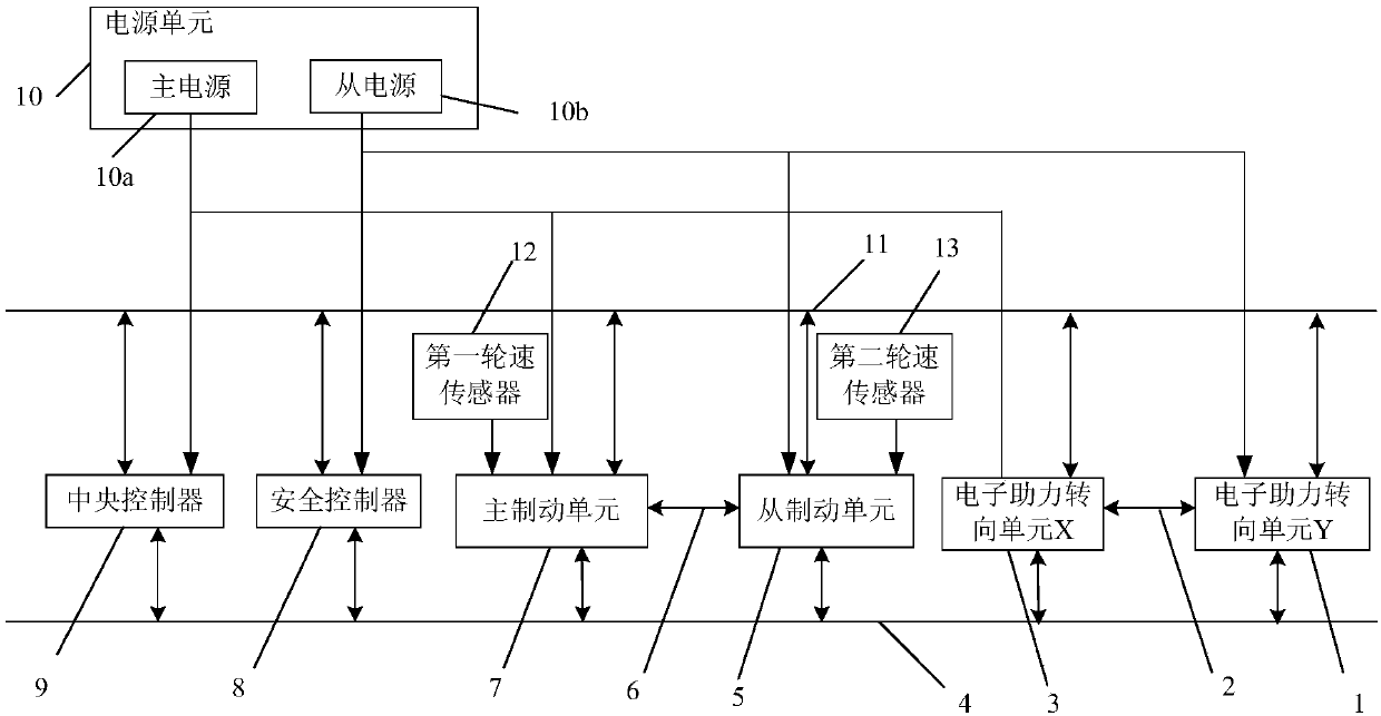
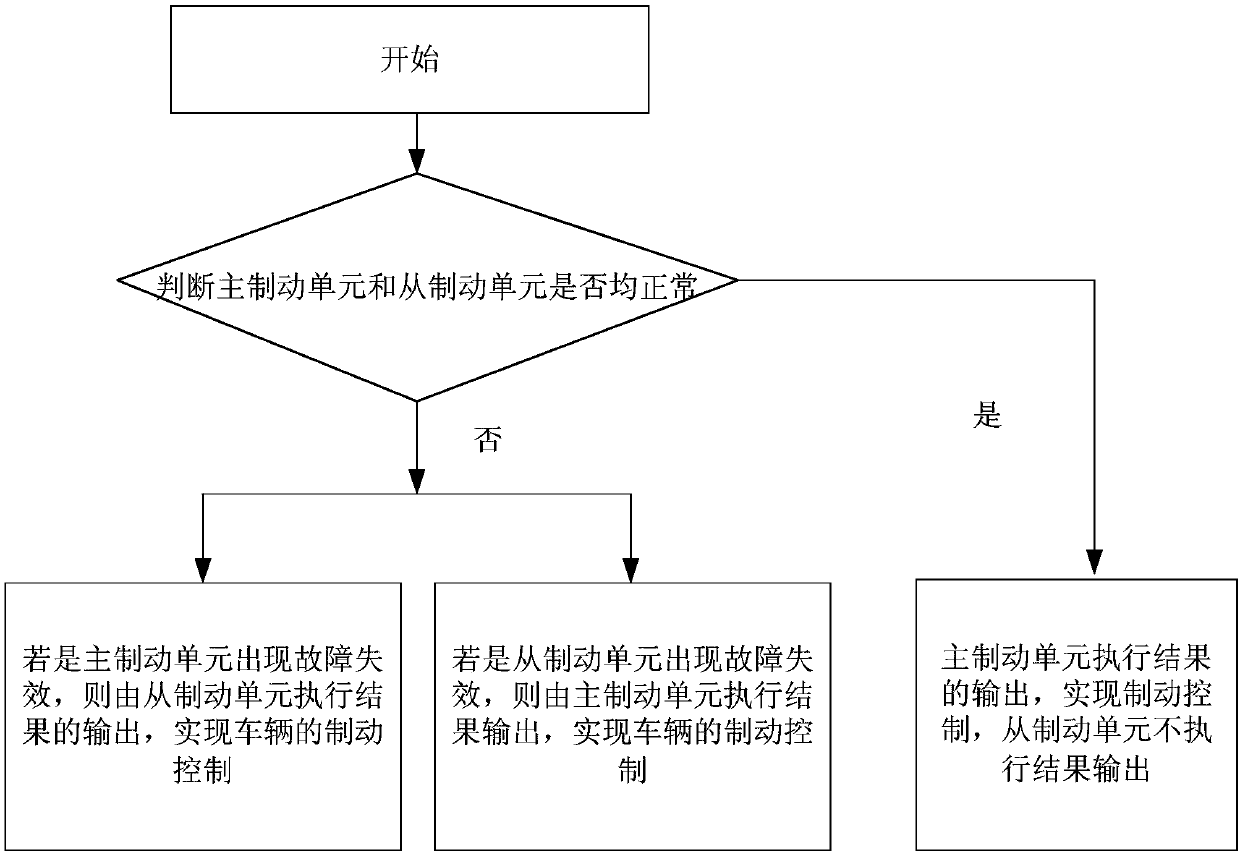
[0045] Such as figure 1 with Figure 4 As shown, the redundant electronic steering braking system of the present invention includes two electronic power steering units (namely electronic power steering unit X3 and electronic power steering unit Y1), master braking unit 7, slave braking unit 5 and Central controller9. Among them, the central controller 9 is used for computing and decision-making automatic driving functions on the vehicle.
[0046] Two electronic power steering units (that is, EPS systems) are used to jointly control the steering of the vehicle; wherein, each of the electronic power steering units (that is, EPS) includes a processor, and a corner torque sensor and a motor that are respectively connected to the processor . Wherein, the rotation angle torque sensor is used to output the actual torque signal and angle signal of the current steering wheel, and send them to the processor connected thereto. The processor is used to obtain the current desired steer...
Embodiment 2
[0074] Such as figure 1 As shown, the redundant electronic steering brake system also realizes the redundancy of the vehicle bus. The vehicle bus includes a first vehicle bus 11 and a second vehicle bus 4; the first vehicle bus 11 is used to transmit feedback of control commands and status signals; the first vehicle bus 11 is also used to transmit current expected steering wheel angle signals. The second vehicle bus 4 is used to transmit the feedback of the control command and status signal synchronously with the first vehicle bus 11 , and the second vehicle bus 4 is also used to transmit the current expected steering wheel angle signal.
[0075] Both electronic power steering units, the master brake unit 7 and the slave brake unit 5 are connected to the first vehicle bus 11 .
[0076] Both electronic power steering units, the master brake unit 7 and the slave brake unit 5 are also connected to the second vehicle bus 4 .
[0077] Such as Image 6 As shown, when one of the v...
Embodiment 3
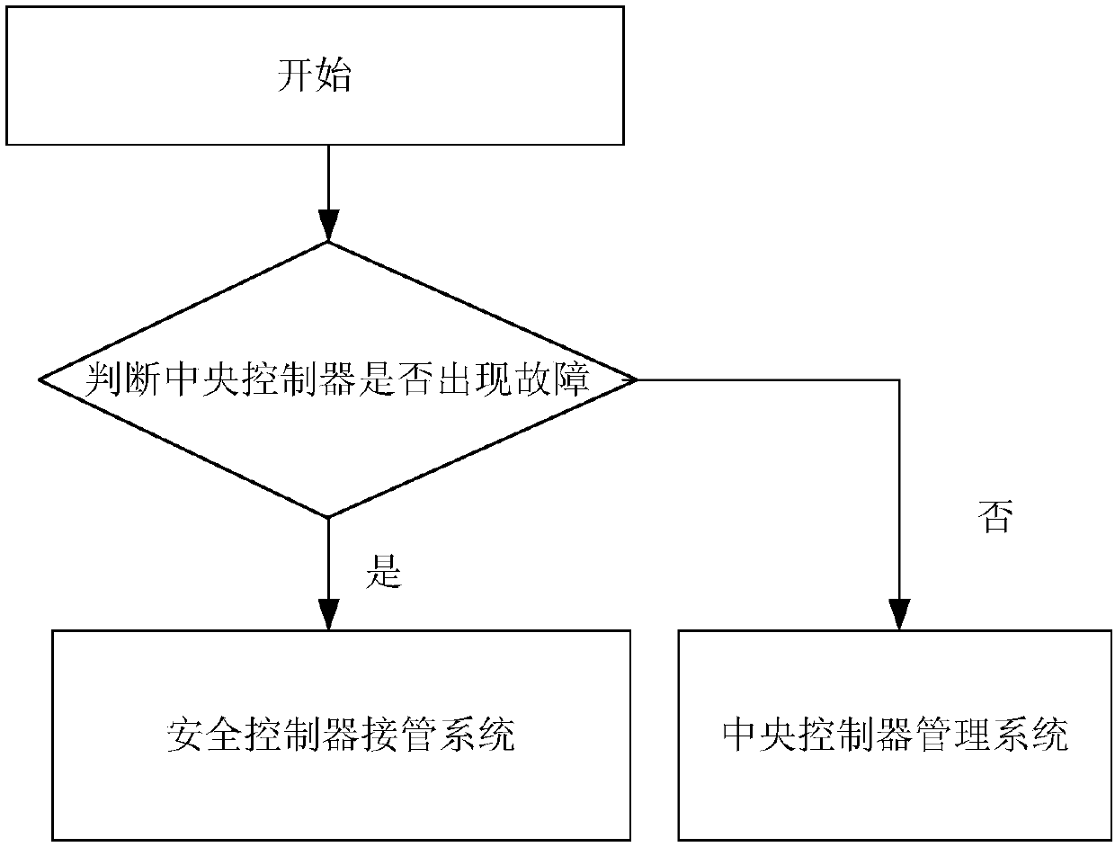
[0086] Such as figure 1 As shown, the redundant electronic steering braking system also includes a safety controller 8, which realizes the redundancy of the controller.
[0087] The central controller 9 is connected with the first automobile bus 11 and the second automobile bus 4 respectively, and the central controller 9 is used for calculating the steering wheel angle signal of the current expectation, and for sending control instructions and monitoring the master brake unit 7 and the slave brake unit 7. The working state of the driving unit 5, and the current desired steering wheel angle signal and control instructions are sent to the first vehicle bus 11 and the second vehicle bus 4 respectively.
[0088] Safety controller 8 is connected with the first automobile bus 11 and the second automobile bus 4 respectively; This safety controller 8 is used for calculating the steering wheel angle signal of current expectation, when monitoring that central controller 9 is not ineffe...
PUM
 Abstract
Description
Claims
Application Information
 - R&D
- Intellectual Property
- Life Sciences
- Materials
- Tech Scout
- Unparalleled Data Quality
- Higher Quality Content
- 60% Fewer Hallucinations
Browse by: Latest US Patents, China's latest patents, Technical Efficacy Thesaurus, Application Domain, Technology Topic, Popular Technical Reports.
© 2025 PatSnap. All rights reserved.Legal|Privacy policy|Modern Slavery Act Transparency Statement|Sitemap|About US| Contact US: help@patsnap.com


