Method for determining a failure in a service or parking brake in a vehicle, regulating or control unit for carrying out the method, and parking brake having such a regulating or control unit

a technology for parking brakes and services, applied in braking systems, analogue processes for specific applications, instruments, etc., can solve problems such as the assumption of errors in hydraulic brake devices, and achieve the effect of reliably detecting failures

Active Publication Date: 2013-09-05
ROBERT BOSCH GMBH
View PDF6 Cites 14 Cited by
  • Summary
  • Abstract
  • Description
  • Claims
  • Application Information

AI Technical Summary

Benefits of technology

[0011]In principle, it is sufficient to examine only one electromotive characteristic or a variable correlating thereto and to infer therefrom damage in the hydraulic system. It may, however, be advantageous to examine multiple variables to minimize the risk of error when detecting a failure, for example.
[0012]The examination of whether an error or a failure is present is advantageously carried out during the operation of the hydraulic brake device for generating a clamping force. In this case, there is a significantly determinable influence on the electromotive characteristics by the hydraulic system due to both the electromotive brake device and the hydraulic brake device having an effect on the same brake piston. As a result, failures are easily determinable.
[0016]If a failure is detected, an error signal is generated which may be processed in various ways. The failure may be displayed to the driver, in particular visually, acoustically, and / or haptically, in order to make her / him aware of the failure. Additionally or alternatively, it is also possible to initially lock the parking brake according to the driver's intention upon detection of a failure, e.g., an overload of the parking brake, but to immediately release it again after the failure is detected to avoid component damage. It is, however, also possible to keep the parking brake locked, but to prompt the driver to release it manually. It may furthermore be advantageous either to operate the parking brake once again automatically after it has been released as soon as a critical value in the hydraulic system again reaches an uncritical range or to communicate to the driver a corresponding request for the parking brake operation.

Problems solved by technology

If the examined electromotive characteristic is outside the admissible value range, an error in the hydraulic brake device must be assumed.

Method used


Image

  • Method for determining a failure in a service or parking brake in a vehicle, regulating or control unit for carrying out the method, and parking brake having such a regulating or control unit
  • Method for determining a failure in a service or parking brake in a vehicle, regulating or control unit for carrying out the method, and parking brake having such a regulating or control unit
  • Method for determining a failure in a service or parking brake in a vehicle, regulating or control unit for carrying out the method, and parking brake having such a regulating or control unit

Examples


Embodiment Construction

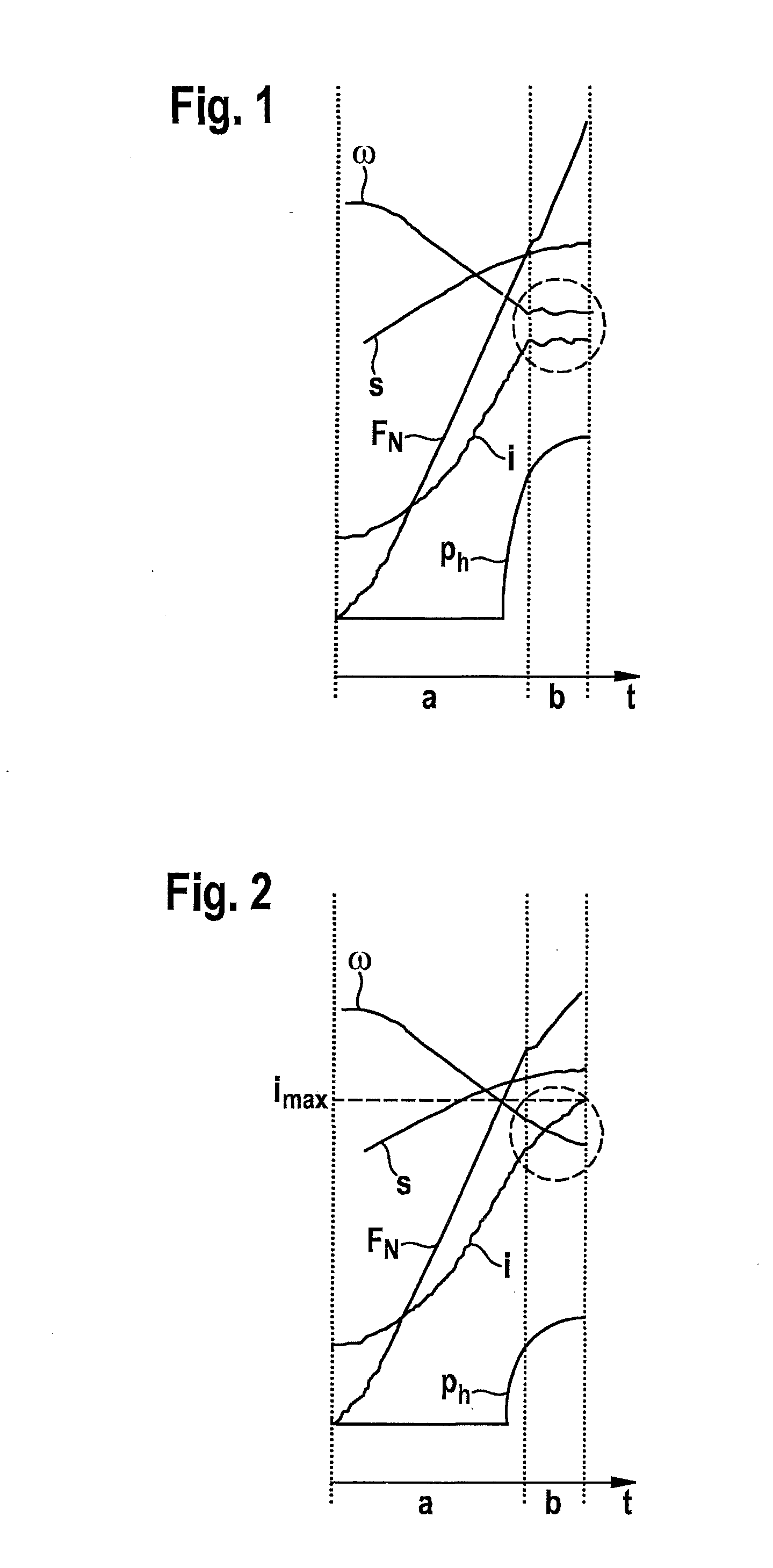
[0023]In FIGS. 1 and 2, the characteristic curve of various characteristics of a parking brake in a vehicle is illustrated chronologically. Hydraulic pressure ph of a hydraulic brake device, current i of an electric brake motor, motor speed ω of the brake motor, actuator travel s of the brake motor, as well as total clamping force FN, which is composed of a portion of the electric brake motor and a portion of the hydraulic brake device, are plotted. FIGS. 1 and 2 each show two chronologically consecutive phases a and b; phase a indicates the solely electromechanical force buildup and phase b indicates the electrohydraulic force buildup until target clamping force FN is reached.

[0024]In the regular case according to FIG. 1, current characteristic curve i as well as motor speed ω of the electric brake motor are on an approximately constant level within a relatively narrow admissible value range during phase b as soon as the target clamping force is reached. In the case of a failure of...


PUM


Abstract

In a method for determining a failure in a service or parking brake having an electromotive and a hydraulic brake device for generating a clamping force, an error is detected in the hydraulic brake device if an electromotive characteristic of the electric brake motor is outside an admissible value range.

Description

FIELD OF THE INVENTION[0001]The present invention relates to a method for determining a failure in a service or parking brake in a vehicle.BACKGROUND INFORMATION[0002]Parking brakes which are used to permanently hold a vehicle at a standstill by generating a clamping force are known from the related art. Parking brakes may include an electric brake motor which is used to generate a clamping force directly on the brake piston of the hydraulic vehicle brake. The electric brake motor is dimensioned in such a way that a clamping force may be generated which reliably holds the vehicle up to a defined gradient. In addition to the electromotive clamping force, a clamping force may also be generated via the hydraulic vehicle brake, for example, for gradients which exceed a certain degree.[0003]The precondition for a parking brake to permanently function properly without the risk of component damage is that the hydraulic wheel brakes are not thermally overloaded, e.g., due to intense operati...

Claims


Application Information

Patent Timeline
Patent Type & Authority Applications(United States)
IPC IPC(8): B60T17/22
CPCB60T13/588B60T13/745B60T17/221B60T17/22B60T13/746
Inventor BAEHRLE-MILLER, FRANKBLATTERT, DIETERPUTZER, TOBIAS
Owner ROBERT BOSCH GMBH
Why Eureka
Try Eureka