
Articulating Transforaminal Lumbar Interbody Fusion Inserter Device and Associated Method of Use

a technology of inserter device and lumbar interbody, which is applied in the field of articulating transforaminal lumbar interbody fusion inserter device, can solve the problems of ineffective removal of disc or immobilization of segment, risk of neural lesions, and nerve roots being moved and damaged

Inactive Publication Date: 2009-02-12
CTL MEDICAL CORP
View PDF13 Cites 87 Cited by
  • Summary
  • Abstract
  • Description
  • Claims
  • Application Information

AI Technical Summary

Benefits of technology

[0007]The present invention relates generally to devices and methods for performing spinal and other surgical procedures. More specifically, the present invention relates to an articulating TLIF inserter device and an associated method of use. This TLIF inserter device is configured to relatively simply and easily place and position bone grafts and / or spinal implants in the intervertebral disc spaces of the spine of a patient. Advantageously, the TLIF inserter device is alternatively substantially curved to minimize tissue disruption and substantially straight to maximize inline impaction forces.
[0010]In a further exemplary embodiment, the present invention provides a transforaminal lumbar interbody fusion method for placing, positioning, and inserting a spinal implant into an intervertebral space with minimum tissue disruption and maximum inline impaction forces, including: providing an elongate shaft having a proximal end, a distal end, and an axis; providing an ergonomic handle disposed at the proximal end of the elongate shaft; providing an articulating joint mechanism disposed at the distal end of the elongate shaft; and providing an inserter piece coupled to the articulating joint mechanism, wherein the inserter piece is operable for selectively retaining the spinal implant, and wherein the articulating joint mechanism is operable for selectively actuating the inserter piece between one or more substantially off-axis configurations and a substantially on-axis configuration with respect to the elongate shaft. The transforaminal lumbar interbody fusion method also includes providing a release mechanism disposed one of at and near the ergonomic handle, wherein the release mechanism is coupled to and operable for selectively actuating the articulating joint mechanism. Optionally, the elongate shaft is substantially cylindrical and hollow. The release mechanism is coupled to and operable for selectively actuating the articulating joint mechanism via one or more of a rod and a wire disposed through the elongate shaft. The articulating joint mechanism includes a base, a slotted capstan pivotably coupled to the base, and a locking bar configured to selectively engage / disengage the slotted capstan. The inserter piece includes one or more of a retention tool and a cutting tool. Optionally, the articulating joint mechanism is operable for selectively actuating the inserter piece between one or more substantially 30 to 40-degree off-axis configurations and a substantially 0-degree on-axis configuration with respect to the elongate shaft. Optionally, the inserter piece is selectively articulatable with respect to the articulating joint mechanism.

Problems solved by technology

However, it does not remove the disc or immobilize the segment very effectively.
PLIF, also utilizing a back (posterior) approach, with pedicle screws, plates, or the like removes the disc and immobilize the segment effectively, but nerve roots may be moved and damaged, and there is a risk of neural lesions.
ALIF, utilizing a front (anterior) approach, with pedicle screws, plates, or the like also removes the disc and immobilize the segment effectively, but again nerve roots and blood vessels may be moved and damaged, and there is a risk of neural lesions.

Method used


Image

  • Articulating Transforaminal Lumbar Interbody Fusion Inserter Device and Associated Method of Use
  • Articulating Transforaminal Lumbar Interbody Fusion Inserter Device and Associated Method of Use
  • Articulating Transforaminal Lumbar Interbody Fusion Inserter Device and Associated Method of Use

Examples


Embodiment Construction

[0017]Again, the present invention relates generally to devices and methods for performing spinal and other surgical procedures. More specifically, the present invention relates to an articulating TLIF inserter device and an associated method of use. This TLIF inserter device is configured to relatively simply and easily place and position bone grafts and / or spinal implants in the intervertebral disc spaces of the spine of a patient. Advantageously, the TLIF inserter device is alternatively substantially curved to minimize tissue disruption and substantially straight to maximize inline impaction forces.

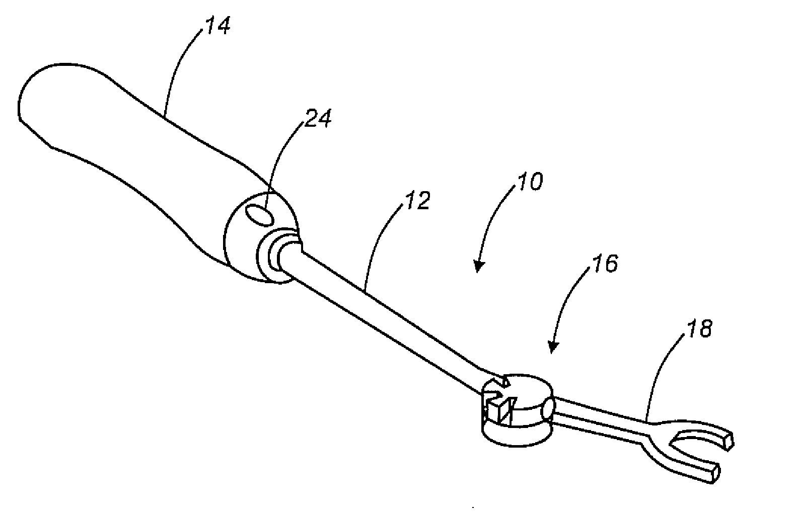
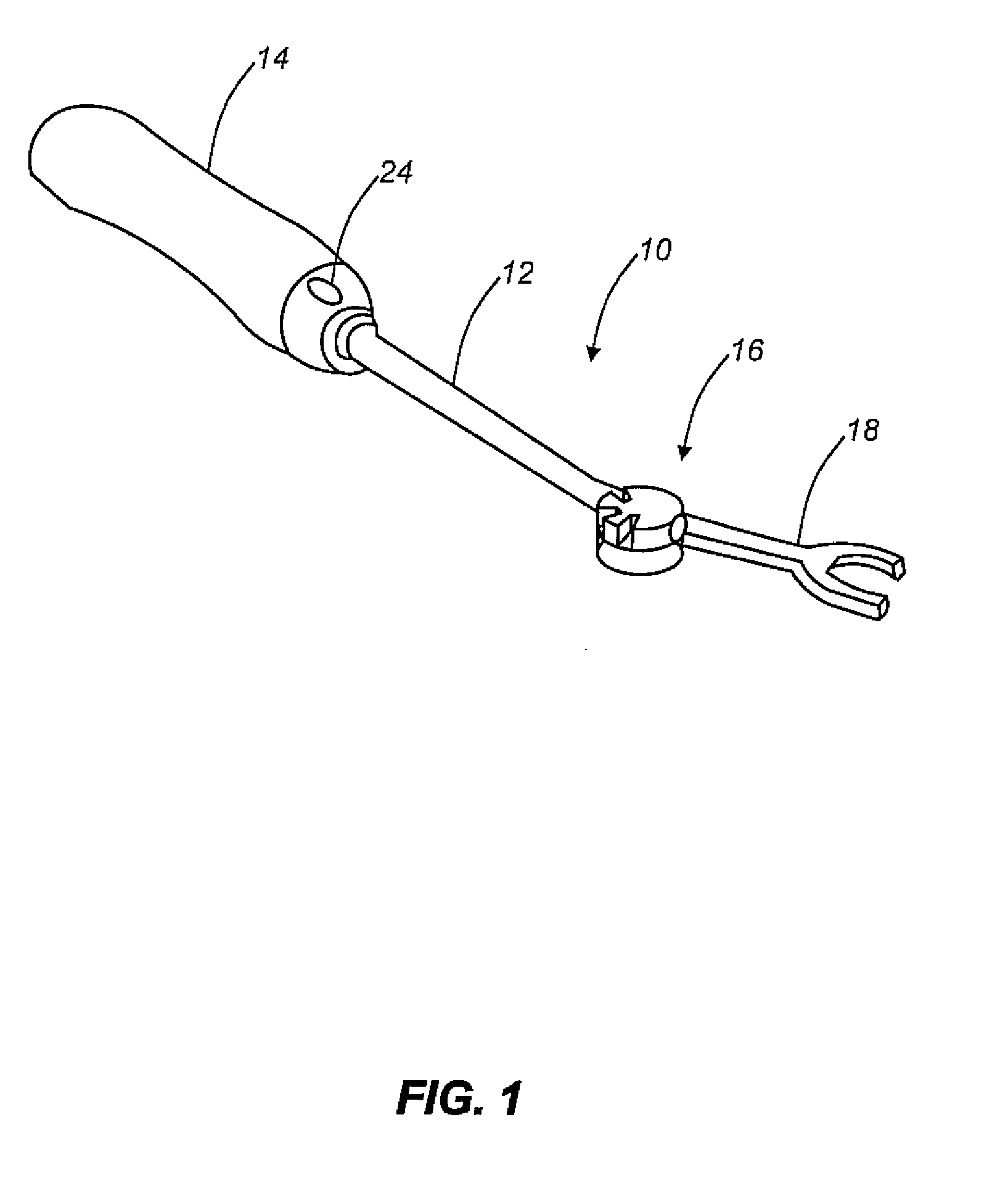
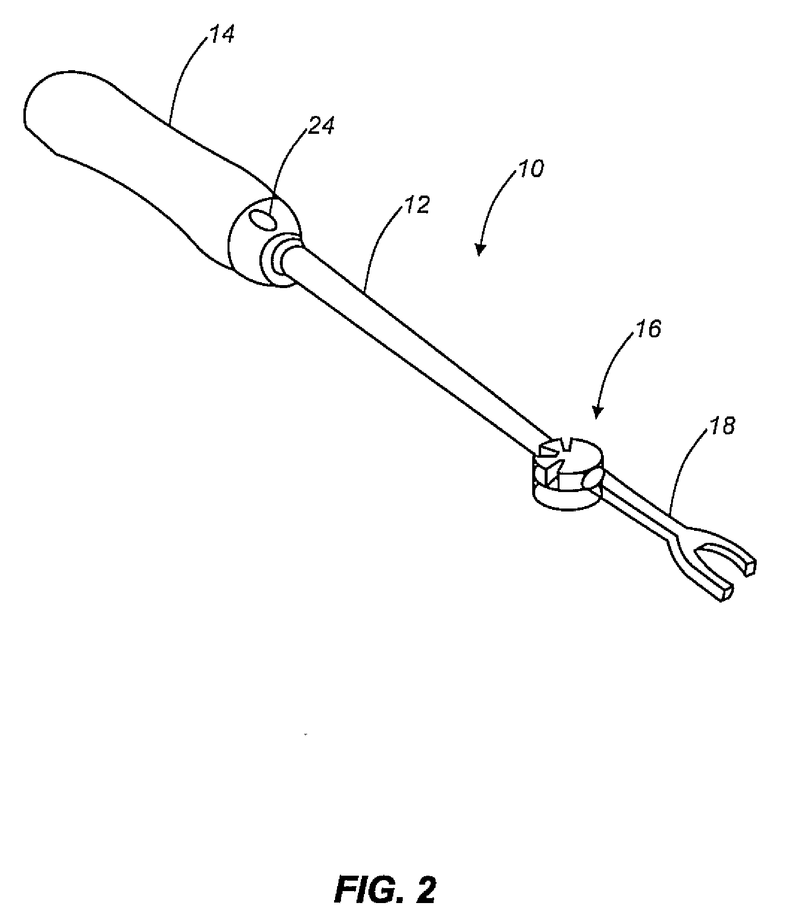
[0018]Referring to FIGS. 1 and 2, in one exemplary embodiment, the TLIF inserter device 10 of the present invention includes an elongate shaft 12 having an ergonomic handle 14 on its proximal end and an articulating joint mechanism 16 on its distal end. An inserter piece 18 or the like rides on the articulating joint mechanism 16, and is selectively movable from off-axis with the shaf...


PUM


Abstract

The present invention provides an articulating TLIF inserter device operable for placing, positioning, and inserting a spinal implant into an intervertebral space with minimum tissue disruption and maximum inline impaction forces, including: an elongate shaft having a proximal end, a distal end, and an axis; an ergonomic handle disposed at the proximal end of the elongate shaft; an articulating joint mechanism disposed at the distal end of the elongate shaft; and an inserter piece coupled to the articulating joint mechanism, wherein the inserter piece is operable for selectively retaining the spinal implant, and wherein the articulating joint mechanism is operable for selectively actuating the inserter piece between one or more substantially off-axis configurations and a substantially on-axis configuration with respect to the elongate shaft. The articulating TLIF inserter device also includes a release mechanism disposed one of at and near the ergonomic handle, wherein the release mechanism is coupled to and operable for selectively actuating the articulating joint mechanism.

Description

CROSS-REFERENCE TO RELATED APPLICATION[0001]The present non-provisional patent application claims the benefit of priority of U.S. Provisional Patent Application No. 60 / 954,132, filed on Aug. 6, 2007, and entitled “ARTICULATING TRANSFORAMINAL LUMBAR INTERBODY FUSION INSERTER DEVICE AND ASSOCIATED METHOD OF USE,” the contents of which are incorporated in full by reference herein.FIELD OF THE INVENTION[0002]The present invention relates generally to devices and methods for performing spinal and other surgical procedures. More specifically, the present invention relates to an articulating transforaminal lumbar interbody fusion (TLIF) inserter device and an associated method of use. This TLIF inserter device is configured to relatively simply and easily place and position bone grafts and / or spinal implants in the intervertebral disc spaces of the spine of a patient. Advantageously, the TLIF inserter device is alternatively substantially curved to minimize tissue disruption and substantia...

Claims


Application Information

Patent Timeline
Patent Type & Authority Applications(United States)
IPC IPC(8): A61B17/58
CPCA61F2002/4628A61F2/4611
Inventor KOULISIS, CHRISTOCROOK, DAVID
Owner CTL MEDICAL CORP
Learn More