Variable valve apparatus

a valve apparatus and variable valve technology, applied in mechanical equipment, valve arrangements, machines/engines, etc., can solve the problems of requiring a certain amount of time for switching from the double valve variable control to the single valve variable control, and no consideration is made in terms of shortening the switching operation time, etc., to achieve the operation time of controlling the variably controlled other valves, small lift, and small operating angle

Inactive Publication Date: 2009-02-19
TOYOTA JIDOSHA KK
View PDF1 Cites 3 Cited by
  • Summary
  • Abstract
  • Description
  • Claims
  • Application Information

AI Technical Summary

Benefits of technology

[0024]According to the third aspect of the present invention, the lift of the valve to be switched can be instantaneously changed to the large lift upon completion of the switching operation. In addition, according to the fourth aspect of the present invention, the operation time for controlling the variably controlled other valves to a sufficiently small lift after the completion of the switching operation can be further shortened.
[0025]According to the fifth aspect of the present invention, at any time after the valve-opening characteristics of the valve to be switched have been changed to the fixed control, the valves other than the valve to be switched are varied in a range with a smaller operating angle or lift than that of the valve to be switched in the predetermined range according to the fifth aspect of the present invention. This prevents a gap from being produced between the second cam and the input arm. As a result, noise or impact load can be prevented from occurring between the second cam and the input arm during the lift operation.
[0026]According to the sixth aspect of the present invention, even with the pin axially misaligned with the pin hole, the rocking member rotates as the pin is guided by the guide surface, bringing the pin into axial alignment with the pin hole. This achieves coupling of the pin. As a result, according to the present invention, the operation time required for the switching operation can be effectively shortened.
[0027]According to the seventh aspect of the present invention, the speed, at which the rocking member moves when coupling of the pin is disengaged, can be decelerated. Accordingly, according to the present invention, noise or impact load that would otherwise occur from a contact between members during disengagement of the coupling of the pin can be prevented.

Problems solved by technology

As such, a certain amount of time is required for switching from the double valve variable control to the single valve variable control.
In the related art mechanism, however, no considerations are made in terms of shortening the switching operation time.

Method used


Image

  • Variable valve apparatus
  • Variable valve apparatus
  • Variable valve apparatus

Examples


first embodiment

[Configuration of a Variable Valve Apparatus]

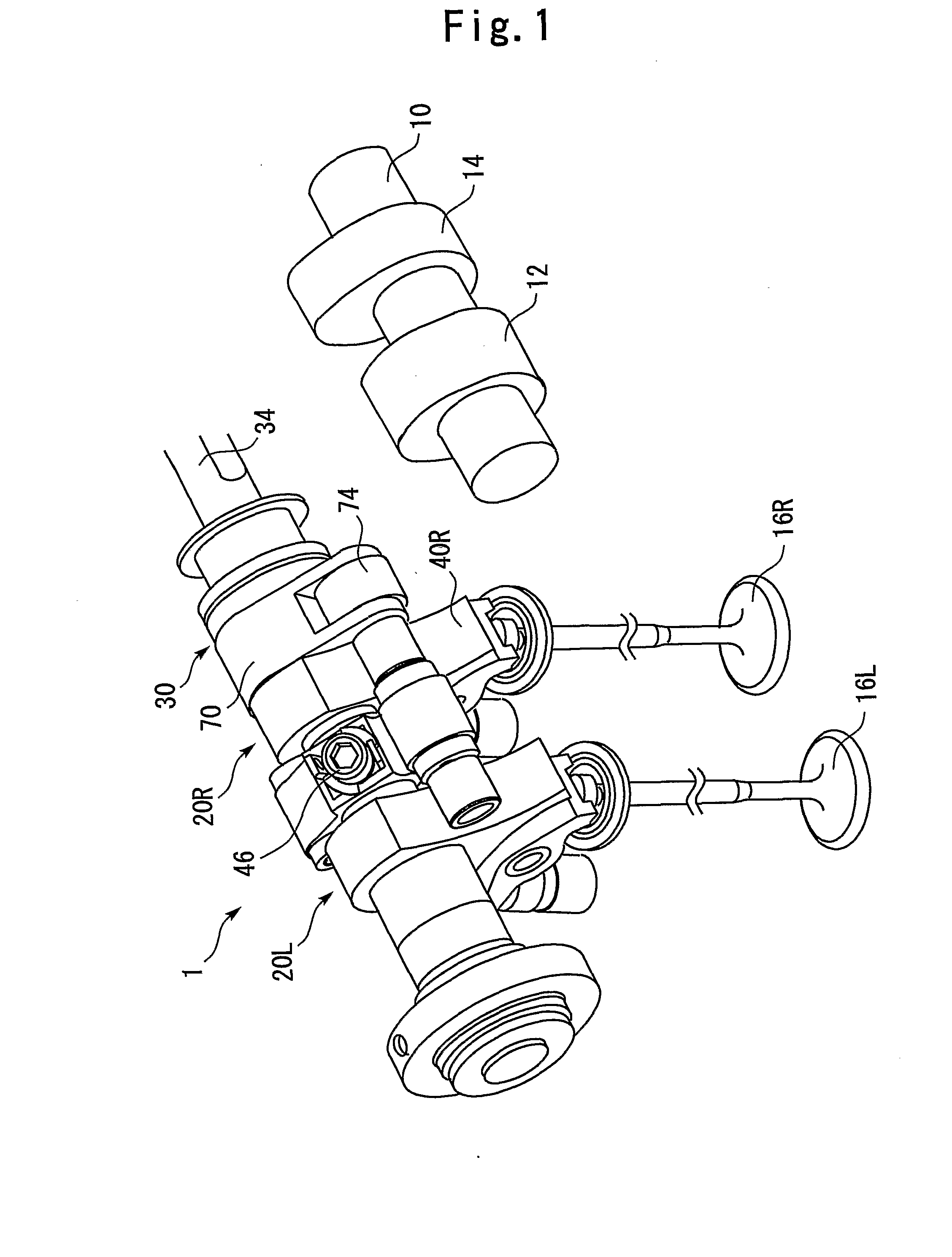
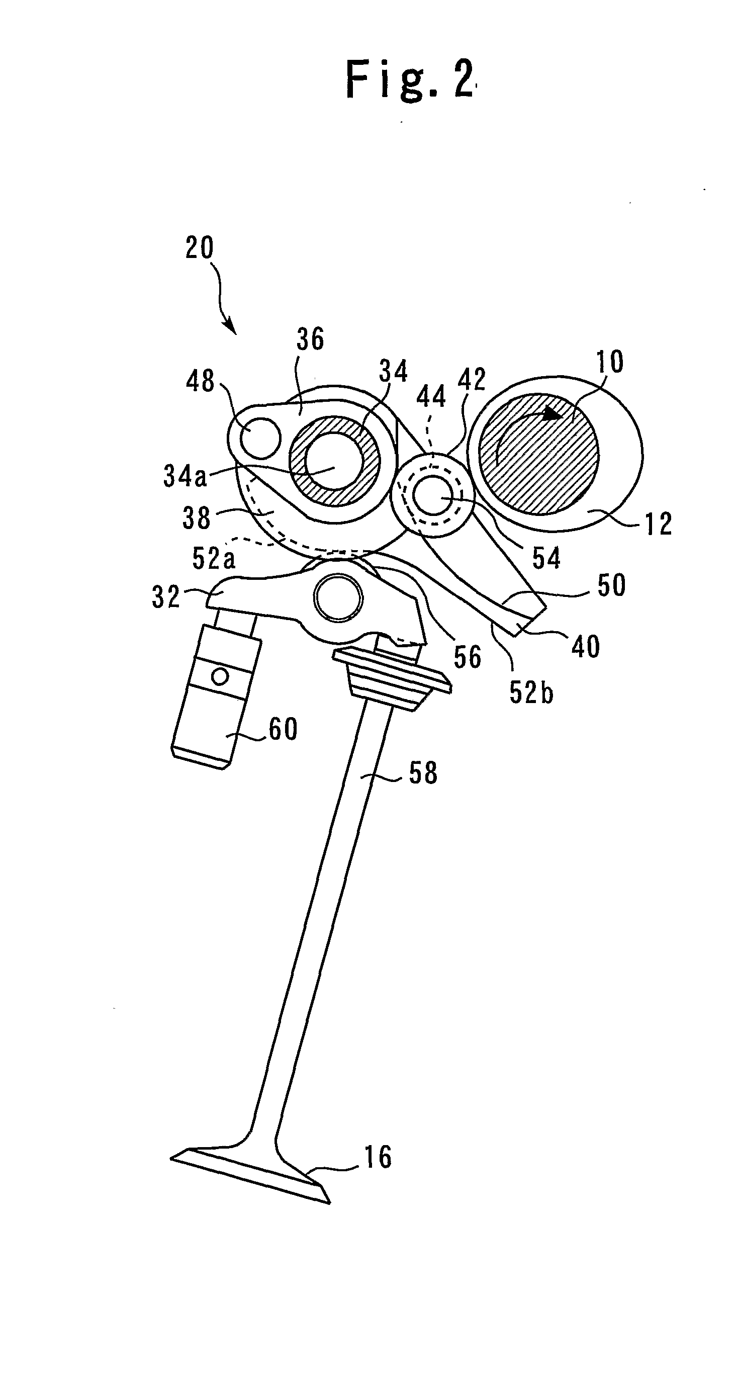
[0046]FIG. 1 is a view for illustrating a mechanism interposed between a driving cam and a valve in a variable valve apparatus 1 according to a first embodiment of the present invention. It is assumed herein that each of the cylinders of the internal combustion engine has two intake valves and two exhaust valves. The arrangement shown in FIG. 1 functions as a mechanism for driving two intake valves or two exhaust valves disposed in a single cylinder.

[0047]Referring to FIG. 1, a camshaft 10 of the variable valve apparatus 1 is provided with two driving cams 12, 14 per cylinder. Two valves—a first valve 16L and a second valve 16R—are symmetrically disposed with respect to one of the two driving cams (a first driving cam) 12. Each of variable valve mechanism 20L, 20R is disposed between the first driving cam 12 and each of the valves 16L, 16R. The variable valve mechanism 20L, 20R operatively couple a lifting movement of each of the valves 1...

second embodiment

[0083]A second embodiment of the present invention will be described below with reference to FIGS. 5 through 8.

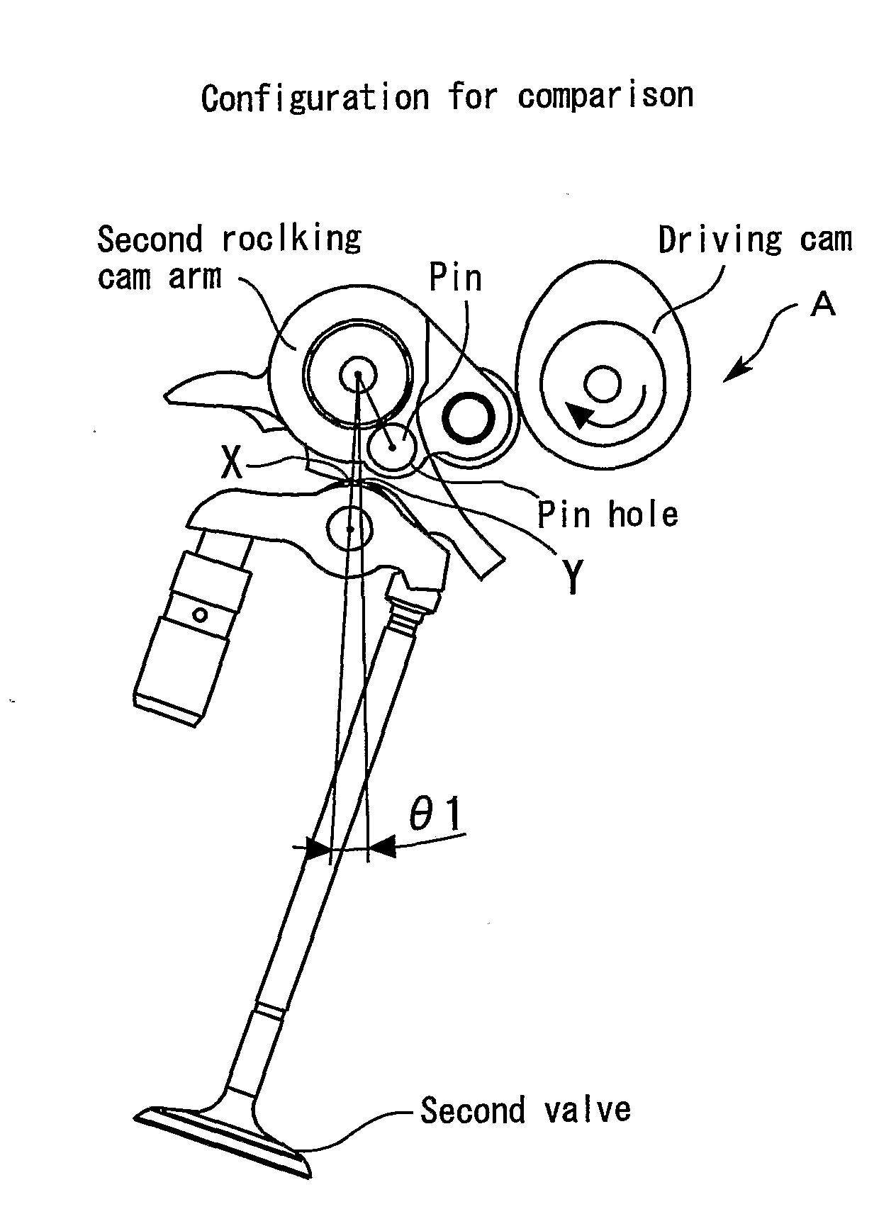
[0084]FIG. 5 is a view for illustrating the arrangement of a variable valve apparatus 90 according to the second embodiment of the present invention. The variable valve apparatus 90 according to the second embodiment of the present invention has the same arrangements as those of the variable valve apparatus 1 according to the first embodiment of the present invention, except for the arrangement of a camshaft 92. Specifically, in the variable valve apparatus 90, too, the position of a pin hole 80 is set so that the pin switching operation can be executed when a second rocking cam arm 40R is in a posture for achieving an operating angle for the operating range required for the switching operation (pin switching operation) from the double valve variable control to the single valve variable control.

[0085]Referring to FIG. 5, the variable valve apparatus 90 has the same arrangem...

third embodiment

[0089]A third embodiment of the present invention will be described below with reference to FIGS. 9 through 11(A) and 11(B).

[0090]A variable valve apparatus 110 according to the third embodiment of the present invention has the same arrangements as those of the variable valve apparatus 1 according to the first embodiment of the present invention, except for the following two points. Specifically, the posture is different of a second rocking cam arm 40R when the switching operation (pin switching operation) from the double valve variable control to the single valve variable control is performed. Further, a second driving cam 114 differs in height from a first driving cam 112.

[0091]FIG. 9 shows a torque curve diagram for illustrating the operating range, in which the single valve variable control is executed, in the variable valve apparatus 110 according to the third embodiment of the present invention. Referring to FIG. 9, the double valve variable control, in which both valves are s...


PUM


Abstract

An arm coupling mechanism for selectively switching a double valve variable control and single valve variable control. The single valve variable control is achieved in a condition in which a large lift arm and a second rocking cam arm are coupled together with a pin. The second rocking cam arm for moving a second valve includes a pin hole, in which the pin is inserted, formed therein. The position of the pin hole is set so that a pin switching operation can be executed when control is provided to achieve an operating angle, at which the single valve variable control is to be started for reduced NOx. A second driving cam is adapted to have a cam height greater than a cam height of a first driving cam.

Description

TECHNICAL FIELD[0001]The present invention relates to a variable valve apparatus and, more particularly, to a variable valve apparatus for an internal combustion engine capable of mechanically changing valve-opening characteristics of a valve.BACKGROUND ART[0002]Patent Document 1, for example, discloses a variable valve apparatus for an internal combustion engine capable of mechanically changing valve-opening characteristics of a valve. Fixed to a single camshaft in this variable valve apparatus are two rotary cams, a first rotary cam and a second rotary cam. Of two intake valves—a first intake valve and a second intake valve—disposed in a single cylinder, the first rotary cam drives to open or close the first intake valve and the second rotary cam drives to open or close the second intake valve. A variable valve transmission mechanism including a four-bar linkage is each disposed between the first rotary cam and the first intake valve and between the second rotary cam and the secon...

Claims


Application Information

Patent Timeline
Patent Type & Authority Applications(United States)
IPC IPC(8): F01L1/26F01L13/00
CPCF01L1/267F01L2013/0068F01L13/0063F01L13/0036
Inventor EZAKI, SHUICHI
Owner TOYOTA JIDOSHA KK
Why Eureka
Try Eureka