
Wireless communication base station apparatus, wireless communication mobile station apparatus, wireless communication method, and wireless communication system

a technology of wireless communication and base station, applied in the field of wireless communication mobile station apparatus, wireless communication method and wireless communication system, can solve the problem of not being able to apply to ue's which receive significant fading variation, and achieve the effect of preventing communication cuto

Inactive Publication Date: 2009-02-19
SOVEREIGN PEAK VENTURES LLC
View PDF5 Cites 8 Cited by
  • Summary
  • Abstract
  • Description
  • Claims
  • Application Information

AI Technical Summary

Benefits of technology

[0020]According to the present invention, it is possible to prevent communication cutoff when RRB arrangement information changes.

Problems solved by technology

Further, the localized channel needs to report the CQI's per RRB frequently, and, for this reason, cannot be applied to UE's which receive significant fading variation.

Method used


Image

  • Wireless communication base station apparatus, wireless communication mobile station apparatus, wireless communication method, and wireless communication system
  • Wireless communication base station apparatus, wireless communication mobile station apparatus, wireless communication method, and wireless communication system
  • Wireless communication base station apparatus, wireless communication mobile station apparatus, wireless communication method, and wireless communication system

Examples


embodiment 1

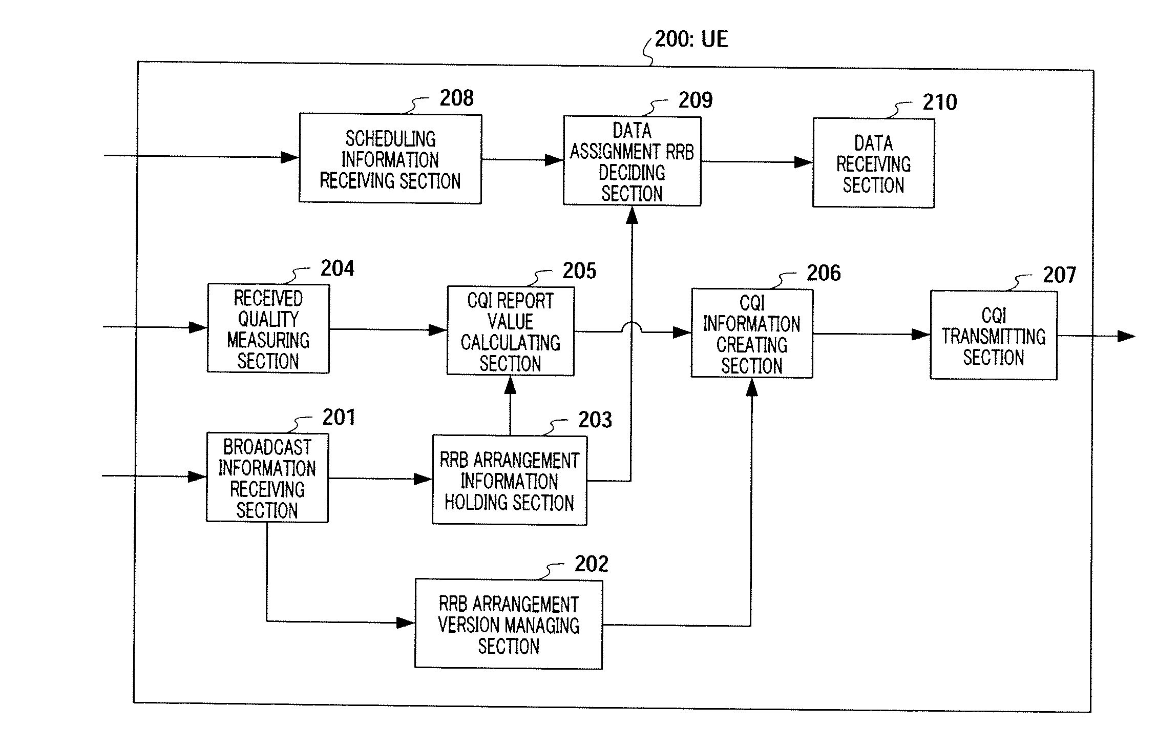
[0035]FIG. 5 is a block diagram showing a configuration of Node B 100 according to Embodiment 1 of the present invention. In this figure, out of UE's under Node B control, RRB arrangement change deciding section 101 decides whether or not to change the RRB arrangement based on, for example, the ratio of the UE's to which the localized channel is applied, and the UE's to which the distributed channel is applied. If RRB arrangement change deciding section 101 decides to change the RRB arrangement, RRB arrangement change information deciding section 101 reports the decision result showing this decision to RRB arrangement version managing section 102 and RRB arrangement changing section 103. If RRB arrangement change deciding section 101 decides to change the RRB arrangement, RRB arrangement change deciding section 101 reports, for example, the changed ratio of the UE's to which the localized channel is applied, and the UE's to which the distributed channel is applied, with the decision...

embodiment 2

[0065]FIG. 10 is a block diagram showing a configuration of Node B according to Embodiment 2 of the present invention.

[0066]FIG. 10 differs from FIG. 5 in removing RRB arrangement version detecting section 105, changing RRB arrangement version managing section 102 to RRB arrangement change timing determining section 301, changing RRB arrangement changing section 103 to RRB arrangement changing section 302, changing RRB arrangement information holding section 106 to RRB arrangement information holding section 303 and changing broadcast information creating section 107 to broadcast information creating section 304.

[0067]In FIG. 10, RRB arrangement change timing determining section 301 acquires a result of deciding to change the RRB arrangement, from RRB arrangement change deciding section 101 and determines the timing to change RRB arrangement information. Information of the determined timing is outputted to RRB arrangement information holding section 303 and broadcast information cre...


PUM


Abstract

A wireless communication method and a wireless communication system wherein any communication interruption caused by changing RRB arrangement information can be avoided. In ST301, Node B (100) transmits informative information including the RRB arrangement information and RRB arrangement version. In ST302, UE (200) holds the RRB arrangement information and RRB arrangement version included in the informative information received from Node B (100). In ST303, UE (200) creates CQI information including both a CQI report value, which is calculated by use of the held RRB arrangement information, and the held RRB arrangement version. In ST304, UE (200) transmits the CQI information to Node B (100). In ST305, Node B (100) performs a scheduling based on the RRB arrangement information determined from the RRB arrangement version included in the received CQI information. In ST306, Node B (100) transmits the scheduling information to UE (200).

Description

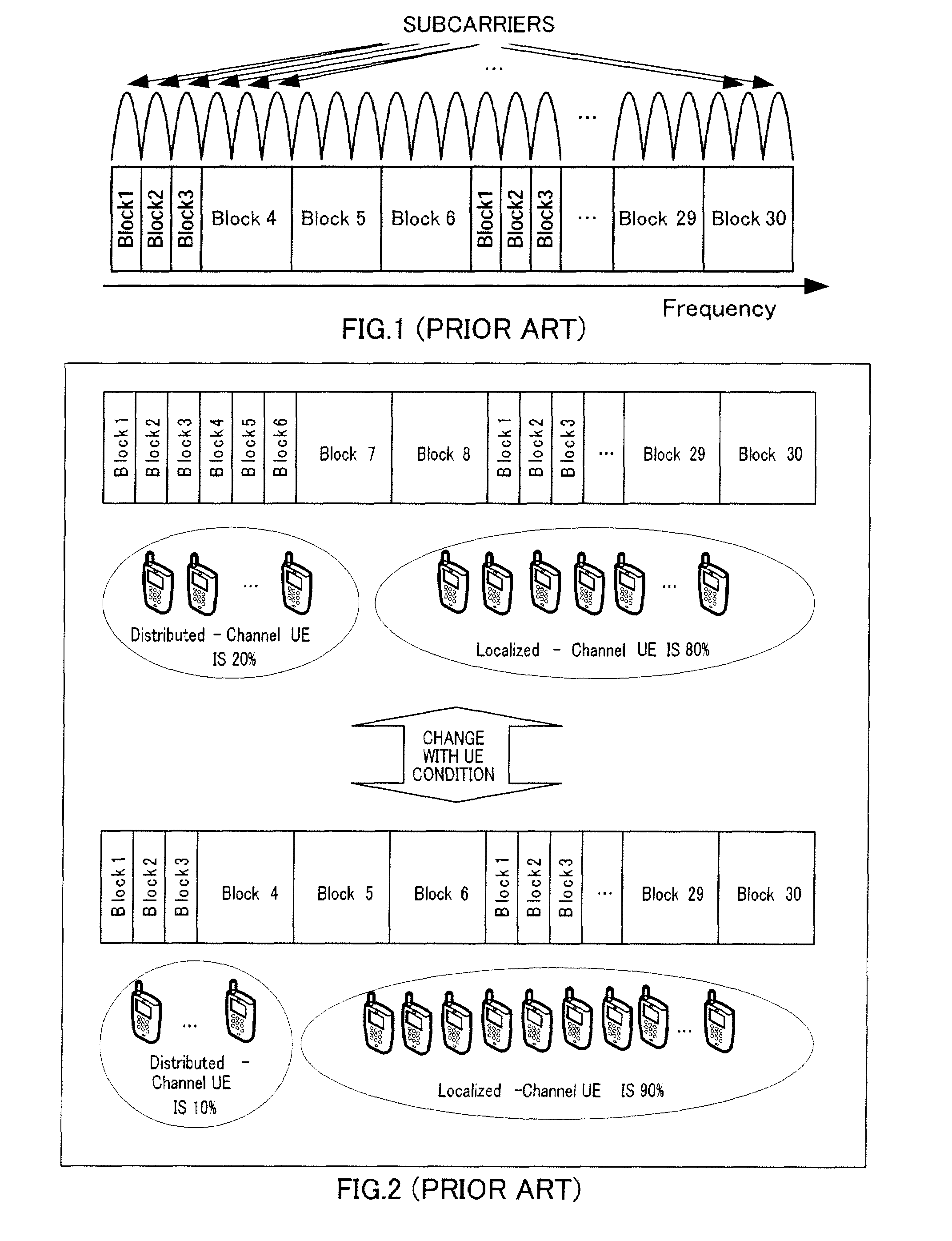
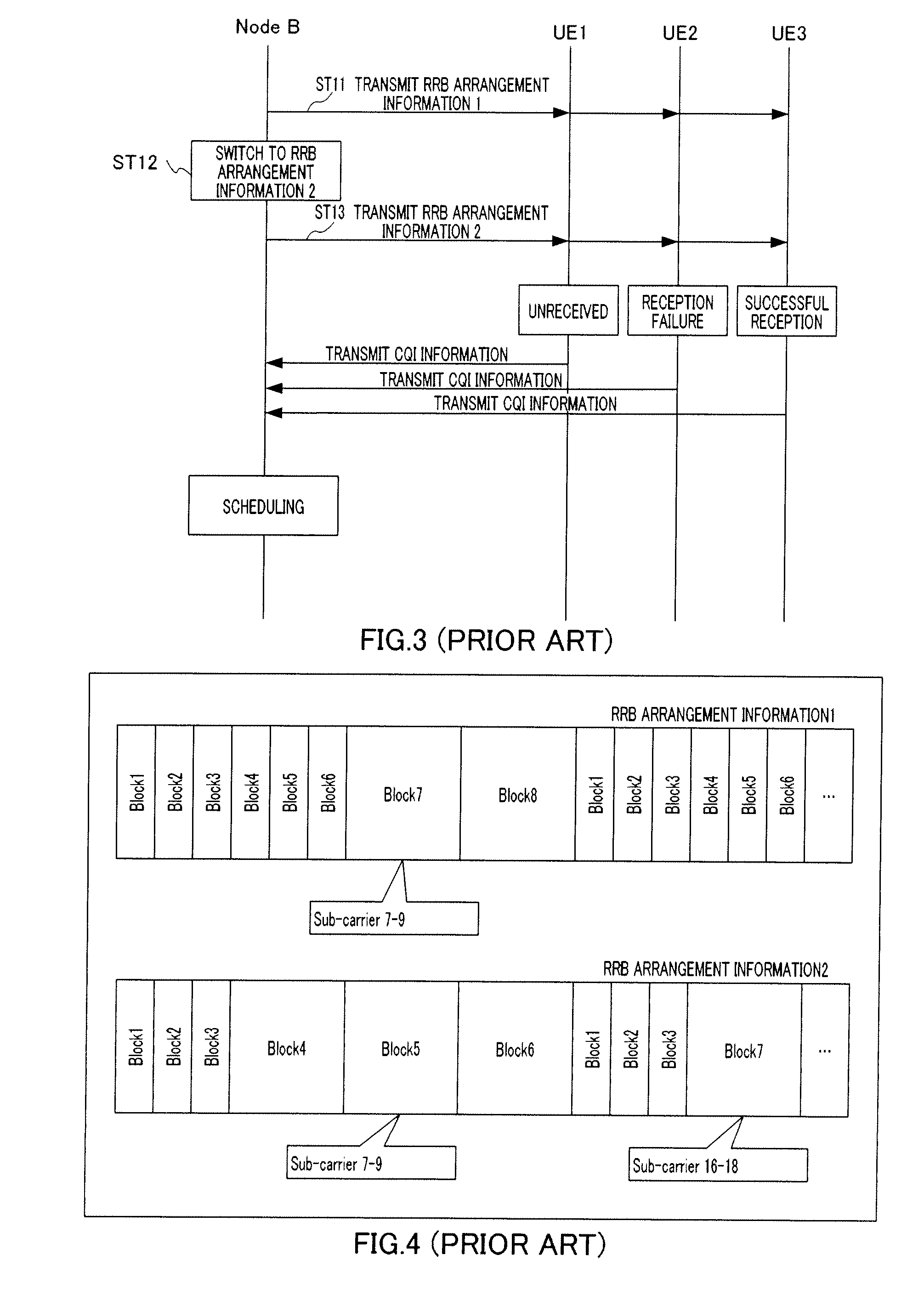
TECHNICAL FIELD[0001]The present invention relates to a wireless communication base station apparatus, wireless communication mobile station apparatus, wireless communication method and wireless communication system that use a localized channel and distributed channel in the OFDM (Orthogonal Frequency Division Multiplex) system.BACKGROUND ART[0002]In recent years, in LTE (Long Term Evolution), carrying out channel definition in the physical layer according to scheduling differences is studied. As specific examples of this channel definition, there are channels such as the localized channel and the distributed channel based on the OFDM system.[0003]FIG. 1 is a conceptual diagram of the localized channel and the distributed channel in the frequency domain. In FIG. 1, blocks 1, 2 and 3 show the distributed channel and blocks 4, 5, 6, . . . , 29 and 30 show the localized channel. Further, in this figure, three subcarriers are assigned to one block of the localized channel. Hereinafter, ...

Claims


Application Information

Patent Timeline
Patent Type & Authority Applications(United States)
IPC IPC(8): G08C15/00H04W72/12
CPCH04W72/1278H04W72/1231H04W72/542H04W72/20H04B7/155H04W16/14H04W88/08
Inventor AOYAMA, TAKAHISANISHIO, AKIHIKOFUKUI, AKITO
Owner SOVEREIGN PEAK VENTURES LLC
Learn More