Remote control linearly regulated fuel valve

a fuel valve and remote control technology, applied in the field of valve construction, can solve the problems of burner generating a larger flame, increasing heat, and not generally allowing intermediate settings of fuel output by the user,

Inactive Publication Date: 2009-02-19
TENG YUSN
View PDF15 Cites 16 Cited by
  • Summary
  • Abstract
  • Description
  • Claims
  • Application Information

AI Technical Summary

Benefits of technology

[0014]The present invention provides a linearly regulated gas valve system having a slotted conical rotatable plug component that is received in a conical cavity formed in a valve body which can be remotely controlled by the user. The unique configuration of the valve with multiple slotted openings in the cone for fuel flow permits steady adjustment as the flow of fuel is increased from low, medium and high output for combustion in the appliance. The slotted plug serves to establish multiple flow paths through the valve body when rotated to a variety of settings so as to align an opening formed in the cavity wall with an orifice formed in the side of the plug. A rotational orientation in which there is no overlap between the opening in the wall and the orifice in the plug shuts off all flow through the valve.

Problems solved by technology

Such design does not generally allow intermediate settings of fuel output by the user.
Based on the characteristics of RF signals and IR signals, including the ability to travel great distances or penetrate walls, there is a risk that the control signal may be generated accidentally for instance from another room where the appliance is located.
If more heat is requested, then the control signal instructs the valve to allow more fuel to reach the burner, resulting in the burner generating a larger flame and increased heat.
While such conventional gas control systems have each provided some fuel flow adjustment, the single flow outlet of the internal cone limits the adjustable range to either high or low.

Method used


Image

  • Remote control linearly regulated fuel valve
  • Remote control linearly regulated fuel valve
  • Remote control linearly regulated fuel valve

Examples


Embodiment Construction

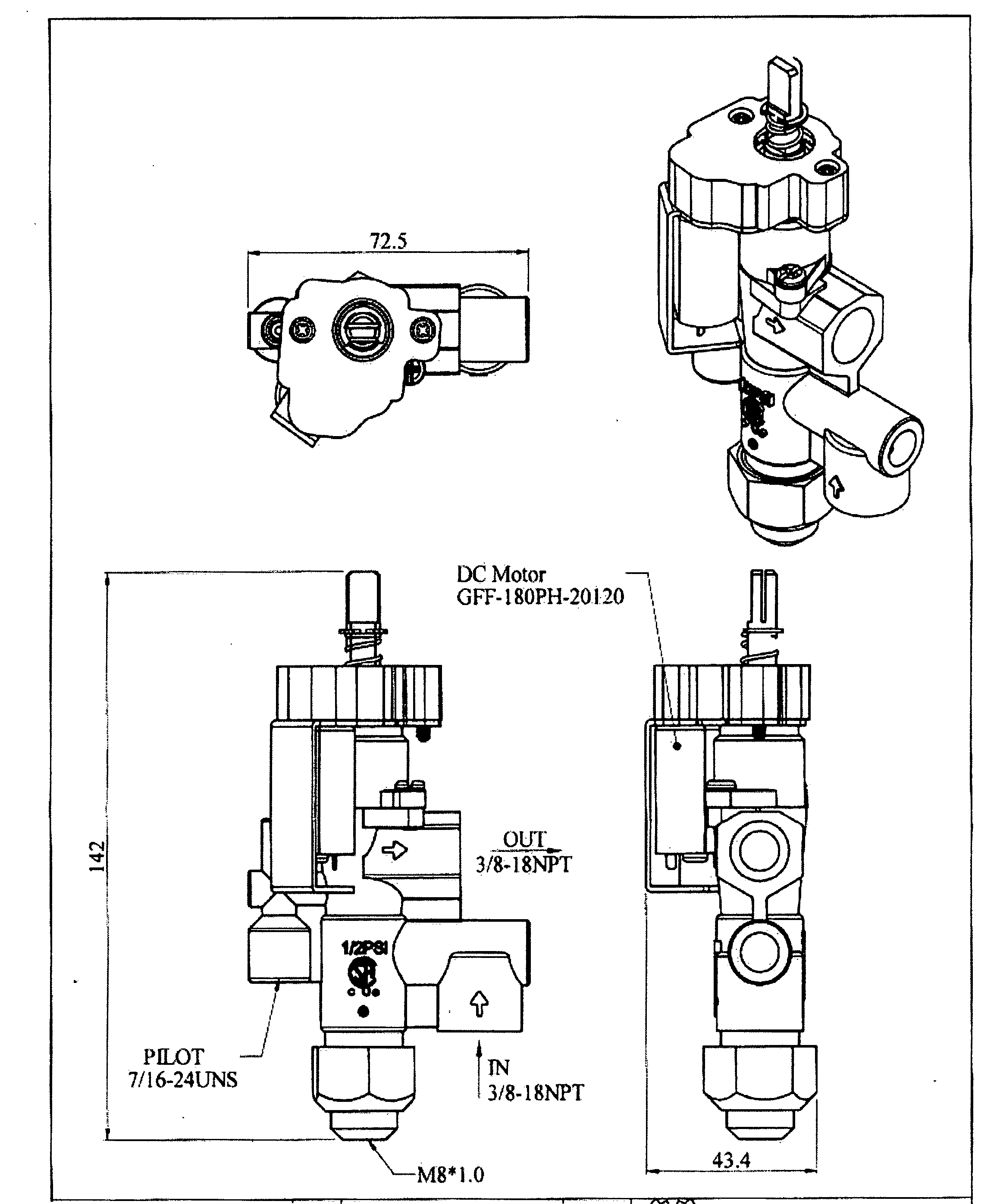
[0030]The present invention generally relates to the construction of valves such as are used to control the flow of combustible gas fired appliances and more particularly pertains to improvements in the configuration and construction of such valves in order to effect linear regulation of gas flow to the burner unit.

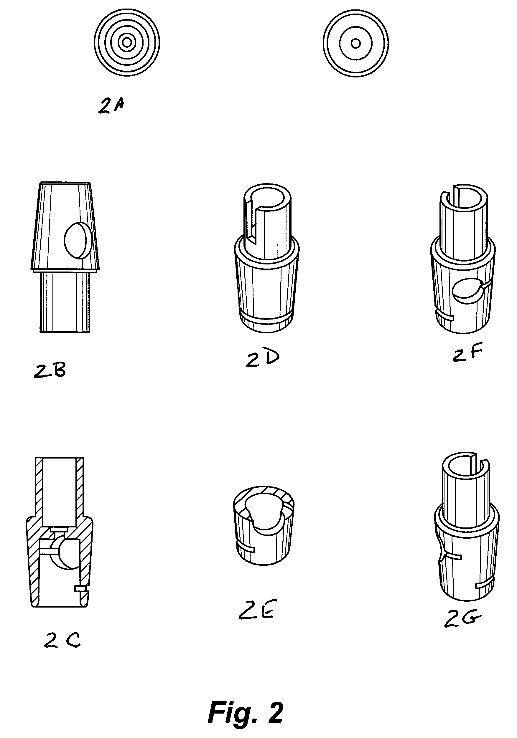
[0031]Conventional design of valve cones in a manual gas valve typically provide a single opening for the flow of fuel. The single opening of cone accordingly limits gas flow to either Low or High output.

[0032]The unique slotted cone of present invention achieves an even linear adjustment of fuel flow. The slot of the cone is rotated for Low, Medium, and High settings to achieve gas flow to main burner at a steady flow rate.

[0033]In more detail, the present invention provides a gas valve that includes a slotted conical rotatable plug component shown most clearly in FIG. 2, that is received in a conical cavity formed in a valve body having an effective seal therebetween. T...


PUM


Abstract

A linearly regulated fuel valve system is provided that includes a slotted conical rotatable plug component that is received in a conical cavity formed in a valve body which can be remotely controlled. The slotted plug serves to establish multiple flow paths through the valve body when rotated so as to align an opening formed in the cavity wall with an orifice formed in the side of the plug. The rotational orientation of the plug with respect to the wall and the orifice in the plug is set by a latch element permitting graduated stepwise adjustment settings such as high, medium, low and shut off of gas flow through the valve. Accordingly, the unique system may be adjusted by remote controlled to a wide range of settings by a single cone having a constant channel for fuel flow.

Description

BACKGROUND OF THE INVENTION[0001]The present invention generally relates to the construction of valves such as are used to control the flow of combustible fuel fired appliances and more particularly pertains to improvements in the configuration and construction of such valves in order to provide linear graduated regulation of fuel flow.[0002]Conventional designs of manual gas valves typically include a “cone” or conical plug having a single opening for regulating the flow of gas to either “Low” or “High” output. Such design does not generally allow intermediate settings of fuel output by the user.[0003]Gas valve control systems can also be used in various applications, including remote controlled heaters and fireplaces. These gas valve control systems typically transmit the control signal as a RF signal or as an infrared (IR) signal. As soon as the receiver receives the control signal, the receiver processes the control signal and operates the appliance in response to the control si...

Claims


Application Information

Patent Timeline
Patent Type & Authority Applications(United States)
IPC IPC(8): F23N1/00
CPCF23N1/005F23N2035/24F23N2035/16F23N2035/14F23N2235/16F23N2235/24F23N2235/14
Inventor TENG, YU-SHAN
Owner TENG YUSN
Why Eureka
Try Eureka