Artificial joint and a joint part intended for this purpose

a technology of artificial joints and joints, applied in knee joints, prostheses, medical science, etc., can solve problems such as tearing of cruciate ligaments, and achieve the effect of low cos

Active Publication Date: 2009-02-19
LIMA CORPORATE SPA
View PDF6 Cites 44 Cited by
  • Summary
  • Abstract
  • Description
  • Claims
  • Application Information

AI Technical Summary

Benefits of technology

[0021]The shaping could be provided in the shape of a drop, tail, or bead. However, it is also particularly simple for the shaping in the transverse plane to have a projection which is configured in the manner of a dovetail connection and which in particular has linearly extending shoulders, in order thus to achieve secure guidance, which requires only small alterations of the artificial joint according to the invention as compared with joints which are known per se. In particular, the mode of operation to be achieved as regards the rolling and sliding movement can thus be combined with the shaping without difficulty.
[0022]In this case, it is particularly expedient if the recess is formed between the convex functional surfaces of the joint part which is in particular associated with the femur, in such a way, for example, that even different joint parts can be combined, and may optionally form a shaping, in such a way that in the case of appropriate indication, a joint part can be subsequently replaced at a comparatively low expense.

Problems solved by technology

Sudden uncontrolled twisting movements of the knee joint, which are not supported by the musculature, can lead to tearing of the cruciate ligaments.

Method used


Image

  • Artificial joint and a joint part intended for this purpose
  • Artificial joint and a joint part intended for this purpose
  • Artificial joint and a joint part intended for this purpose

Examples


Embodiment Construction

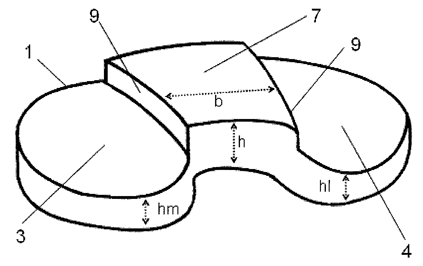
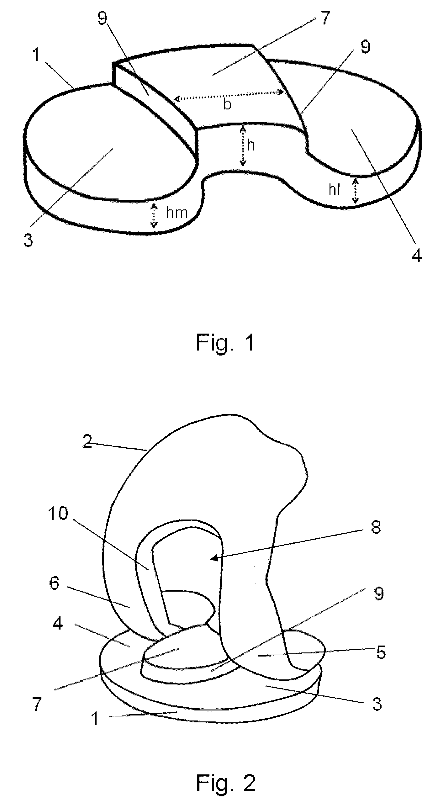
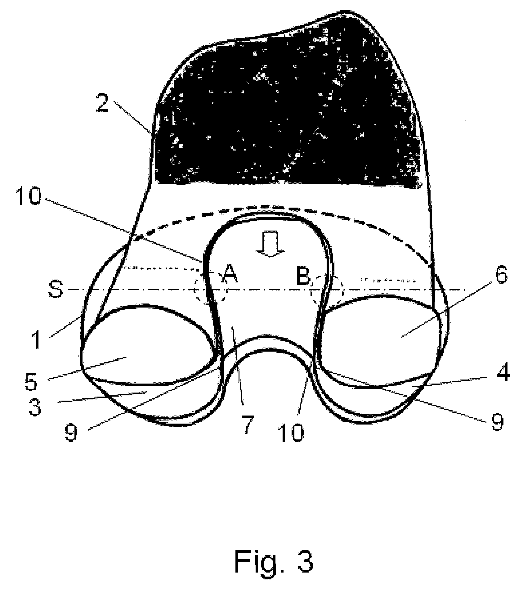
[0033]The artificial joint according to the invention will be explained in greater detail in the following by way of FIGS. 1 to 5, FIG. 1 showing a perspective view of a tibial joint part 1 and FIG. 2 showing a perspective view of an arrangement of the tibial joint part 1 and a femoral joint part 2 as an endoprosthesis for a human knee joint in a highly bent position. Each joint part 1 comprises two functional surfaces 3, 4, each of which cooperates with a functional surface 5, 6 of the other joint part 2, the two functional surfaces 3, 4, 5, 6 of each joint part 1, 2 being formed so as to be spheroidal and convex-concave, concave-convex, or convex-convex in the proximal-distal arrangement. The functional surfaces 3, 4, 5, 6 are formed in such a way that upon extension / flexion of the joint, a combination of a rolling and a sliding movement occurs. In order to provide, in each bending position, a posterior blocking means which corresponds to the rear cruciate ligament, and moreover t...


PUM


Abstract

An artificial joint as an endoprosthesis for a human joint, including a first joint part having two first functional surfaces, a second joint part having two second functional surfaces, the two first and second functional surfaces of each joint part being convex-concave, concave-convex, or convex-convex in a proximal-distal direction, a projection associated with the first joint part; and a recess associated with the second joint part. The recess is configured to engage with the projection so as to determine a relative position of the first and second joint parts in a transverse plane of the joint and to form a stop for a sliding movement of the first and second joint parts relative to each other. The two first functional surfaces are pivotable about a pivot axis with respect to the second functional surfaces and each of the first functional surfaces rolls and slides with respect to the second functional surfaces during an extension or flexion of the artificial joint. A respective posterior position in each angular position is determined as a function of the extension/flexion of the first and second joint parts so as to at least partially delimit a posterior sliding movement of first joint relative to the second joint part.

Description

[0001]Priority is claimed to German Patent Application No. DE 10 2007 037 154.5, filed Aug. 7, 2007, the entire disclosure of which is incorporated by reference herein.[0002]The invention relates to an artificial joint as an endoprosthesis for a human joint, in particular a knee joint, consisting of at least two joint parts, each joint part comprising two functional surfaces, the two functional surfaces of each joint part being formed so as to be spheroidal and to be convex-concave, concave-convex, or convex-convex in the proximal-distal arrangement and the functional surfaces being pivotable about one pivot axis in each case, and being formed in such a way that upon extension / flexion of the joint a combination of a rolling and a sliding movement occurs, the artificial joint having a shaping which is formed by a projection associated with the first joint part and a recess associated with the second joint part and which determines the relative position of the two joint parts in the t...

Claims


Application Information

Patent Timeline
Patent Type & Authority Applications(United States)
IPC IPC(8): A61F2/38
CPCA61F2/3886
Inventor NAEGERL, HANS
Owner LIMA CORPORATE SPA
Why Eureka
Try Eureka