Controller for walking assistance device

a technology of assistance device and controller, which is applied in the field of assistance device for walking assistance, can solve the problems of not having a technology to appropriately divide the lifting force between the leg links, the user cannot apply the desired lifting force stably, and the user needs a complicated coordinated control of the actuator, so as to reduce the load on the legs of the user more effectively and reduce the force

Active Publication Date: 2009-02-19
HONDA MOTOR CO LTD
View PDF8 Cites 29 Cited by
  • Summary
  • Abstract
  • Description
  • Claims
  • Application Information

AI Technical Summary

Benefits of technology

[0027]This provides a reliable control of the actual force to be controlled for each leg link (the actual force to be controlled corresponds to the load (a force balanced with the upward lifting force actually applied to the user from the receiving portion) actually applied to the receiving portion from the user and the actual share for each leg link with respect to the total supporting force for supporting the weight X of the walking assistance device or the weight of the entire walking assistance device) to the desired value. Moreover, in this state, the actual lifting force applied to the user from the receiving portion can be controlled to the lifting force corresponding to the force obtained by multiplying the total treading force of the user by the desired assist ratio.
[0028]Thereby, in the sixth invention, while distributing the lifting force which supports the weight obtained by multiplying the total weight of the user by the desired assist ratio to the left and right leg links in such a way as to fit in with the operating states of the legs intended by the user in consideration of the weight of the walking assistance device, the lifting forces can be appropriately applied to the user from the receiving portion. As a result, the loads on the legs of the user can be reduced more effectively.
[0029]Therefore, according to the sixth invention, it is possible to reduce the forces that should be supported by the user on the floor with his / her legs with the portions attached to the legs of the user reduced and to distribute the assisting force (lifting force) for the reduction to the leg links corresponding to the legs of the user appropriately.

Problems solved by technology

This easily causes a displacement of the user's contact position with respect to the support member and therefore it is practically impossible to cause the user to apply a desired lifting force stably while supporting a part of the user's weight.
In that case, however, there is a need for a complicated coordinated control of the actuators for the first joint and the second joint of each leg link.
The walking assistance device of Patent Document 1, however, does not have a technology to appropriately divide the lifting force between the leg links.
Therefore, there has been a possibility that a force which does not match the movement of each leg of the user is applied to the corresponding leg.

Method used


Image

  • Controller for walking assistance device
  • Controller for walking assistance device
  • Controller for walking assistance device

Examples


first embodiment

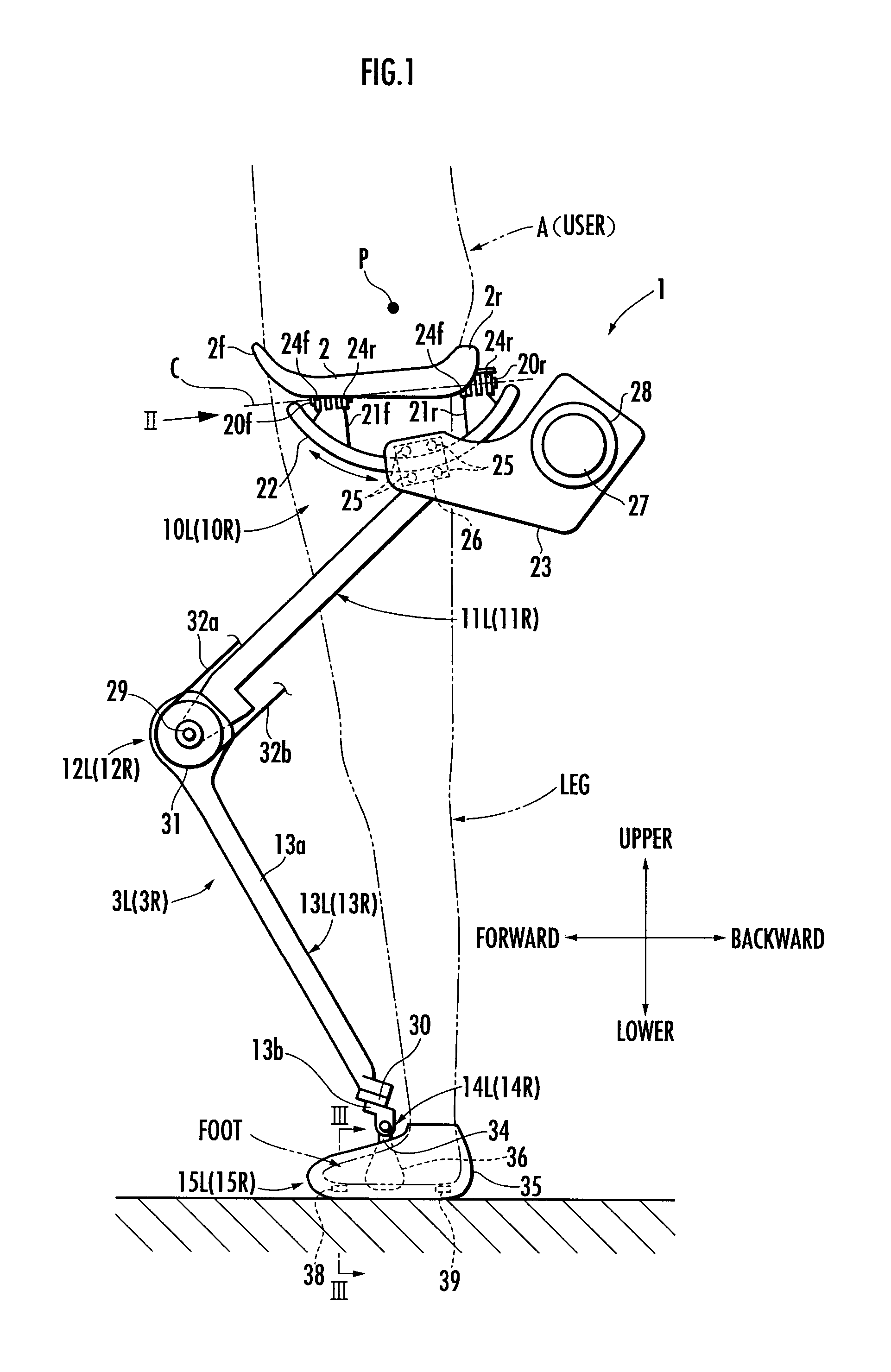
[0149]In the first embodiment described hereinabove, the line of action of the supporting force (translational force) transmitted from the third joint 14 of each leg link 3 to the crus frame 13 is substantially the same as a straight line which passes through the forward / backward swing central point P existing above the seat member 2 within the width in the anteroposterior direction of the contact surface between the seat member 2 and the user A from the central point of the third joint 14. Then, each leg link 13 is free to swing in the forward / backward direction with respect to the seat member 2 with the forward / backward swing central point P as a fulcrum. Therefore, the position and posture of the seat member 2 balance out in a state where an action point (more specifically, a center of gravity of a load distributed over the contact surface between the user A and the seat member 2) of a load applied to the seat member 2 from the user A (a translational force which is balanced with...

fifth embodiment

[0187]In the embodiments described above, the first force sensor is composed of the MP sensor 38 and the heel sensor 39, these sensors 38 and 39 being provided in the foot attachment portions 15 so that they are located between the sole of the foot of a standing leg of the user A and a floor, as shown in FIG. 3. The mounting position of the first force sensor, however, is not limited thereto. The first force sensor can alternatively be provided in the foot attachment portion as shown in, for example, FIG. 18. This case will be described below as a

[0188]Referring to FIG. 18, in the fifth embodiment, a foot supporting member 100 is provided inside the annular member 36 of a foot attachment portion 15. The foot supporting member 100 shaped like a slipper is composed of a plate-like foot sole member 101 (a member like an insole of a shoe) that comes in contact with substantially the entire sole of a foot of a user A and an arched member 102 (a member having a cross section of an approxi...

second embodiment

[0209]FIG. 14 is a block diagram showing a functional configuration of an arithmetic processing unit provided in a controller for a walking assistance device according to the present invention;

[0210]FIG. 15 is a block diagram showing a processing flow of left and right desired lifting force share determining means in FIG. 14:


PUM


Abstract

A walking assistance device (1) has a receiving portion (2) which receives a part of the weight of a user (A) applied from above and a pair of left and right leg links (3R, 3L) connected to the receiving portion (2) through first joints (10R, 10L), with foot attachment portions (15R, 15L) at lower ends of the leg links (3R, 3L) attached to the feet of the legs of the user (A), respectively. The leg links (3R, 3L) are connected to the receiving portion (2) in such a way that, when each leg of the user (A) is a standing leg, a line of action of a supporting force transmitted from a third joint (14R, 14L) of the leg link (3R, 3L) to a crus frame (13R, 13L) out of the supporting force acting on the leg link (3R, 3L) from the floor side passes through a specific point (P) located upper than the receiving portion (2) within an anteroposterior width of a contact surface between the receiving portion (2) and the user (A) from the third joint (14R, 14L), viewed in the sagittal plane. Thereby, it is possible to stably apply a desired lifting force for reducing the weight to be borne by the user with his/her legs to the user.

Description

TECHNICAL FIELD[0001]The present invention relates to a walking assistance device for assisting a user (person) in walking.BACKGROUND ART[0002]Conventionally, as this type of walking assistance device, there is known one shown in FIG. 4 of Japanese Patent Laid-Open No. Hei 7 (1995)-112035 (hereinafter, referred to as Patent Document 1), for example. The walking assistance device shown in FIG. 4 of Patent Document 1 has a pair of left and right leg links extending from a frame carried on back of the user's body and foot members at the lower ends of the leg links are attached to the user's feet. It then intends that a saddle-shaped support member extended from the frame to the user's crotch supports a part of the user's weight. Each leg link has a first joint (corresponding to a hip joint) relatively closer to the frame, a second joint (corresponding to a knee joint) in a middle portion, and a third joint (corresponding to an ankle joint) at the lower end.DISCLOSURE OF THE INVENTION[0...

Claims


Application Information

Patent Timeline
Patent Type & Authority Applications(United States)
IPC IPC(8): A61F2/74A61F2/62A61F2/66A61F2/48
CPCA61H3/008A61H2201/1633A61H2201/165B25J9/0006A61H3/00A61H2201/5069A61H2201/1238A61H2201/1642A61H2201/1676A61H2201/5061A61H2201/1215
Inventor IKEUCHI, YASUSHINODA, TATSUYA
Owner HONDA MOTOR CO LTD
Why Eureka
Try Eureka