
Proximity sensor

a proximity sensor and sensor technology, applied in the field of proximity sensors, can solve the problems of poor detection accuracy and large variation of magnetic field, and achieve the effect of improving the detection accuracy of proximity sensors

Active Publication Date: 2009-02-26
HONDA MOTOR CO LTD
View PDF2 Cites 16 Cited by
  • Summary
  • Abstract
  • Description
  • Claims
  • Application Information

AI Technical Summary

Benefits of technology

[0009]In one or more embodiments of the invention, a proximity sensor which may enhance the detect precision thereof.
[0014]According to the first aspect of the invention, since the magnetic detection element may be applied a force toward the detection surface thereof using the elastic member, the distance between the detection surface of the magnetic detection element and the member to be detected may be maintained constant. This may provide an effect that the detect accuracy of the proximity sensor may be enhanced.
[0015]According to the second aspect of the invention, since the magnetic detection element may be fixed between the elastic member and the inner surface of the housing, the distance between the detection surface of the magnetic detection element and the member to be detected may be maintained constant more positively. Therefore, since the relative position between the housing and magnetic detection element may be kept stationary, there may be provided an effect that the detect accuracy of the proximity sensor may be enhanced.
[0017]According to the fourth aspect of the invention, since the elastic member is also formed when forming the housing, there is provided an effect that the formation of the housing and elastic member maybe carried out easily without taking time and labor.

Problems solved by technology

However, in the above-mentioned related proximity sensor, when the relative position relationship between the housing of the proximity sensor and the detect portion thereof is shifted, the magnetic field of the magnetic field generating portion may be varied to thereby worsen the detect precision of the proximity sensor.
In other words, when a distance from the detect portion of the proximity sensor to the member to be detected varies with age, there is a fear that the amount of variation of the magnetic field may be varied to thereby vary the slide detect position of the seat.

Method used


Image

  • Proximity sensor
  • Proximity sensor
  • Proximity sensor

Examples


Embodiment Construction

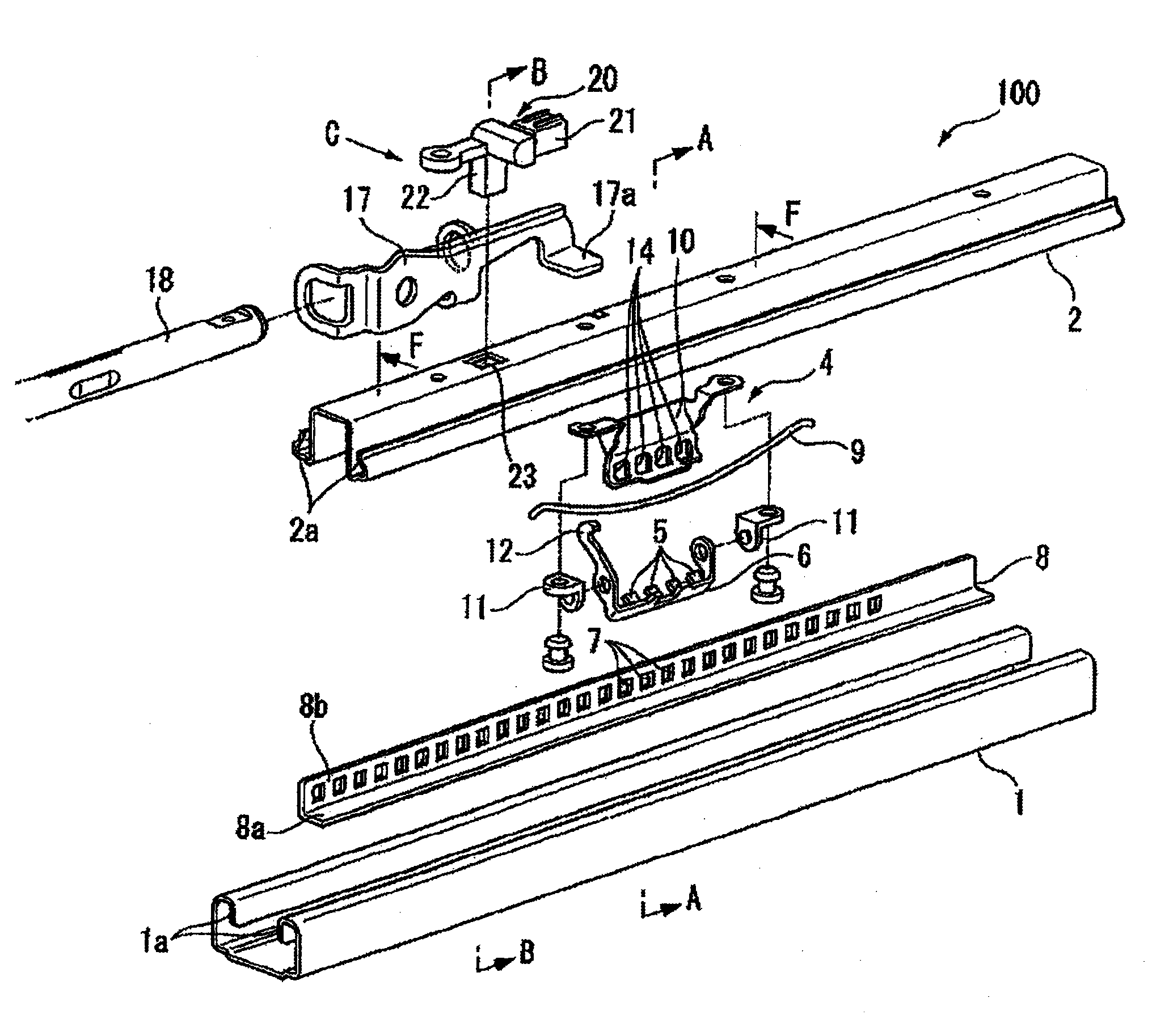
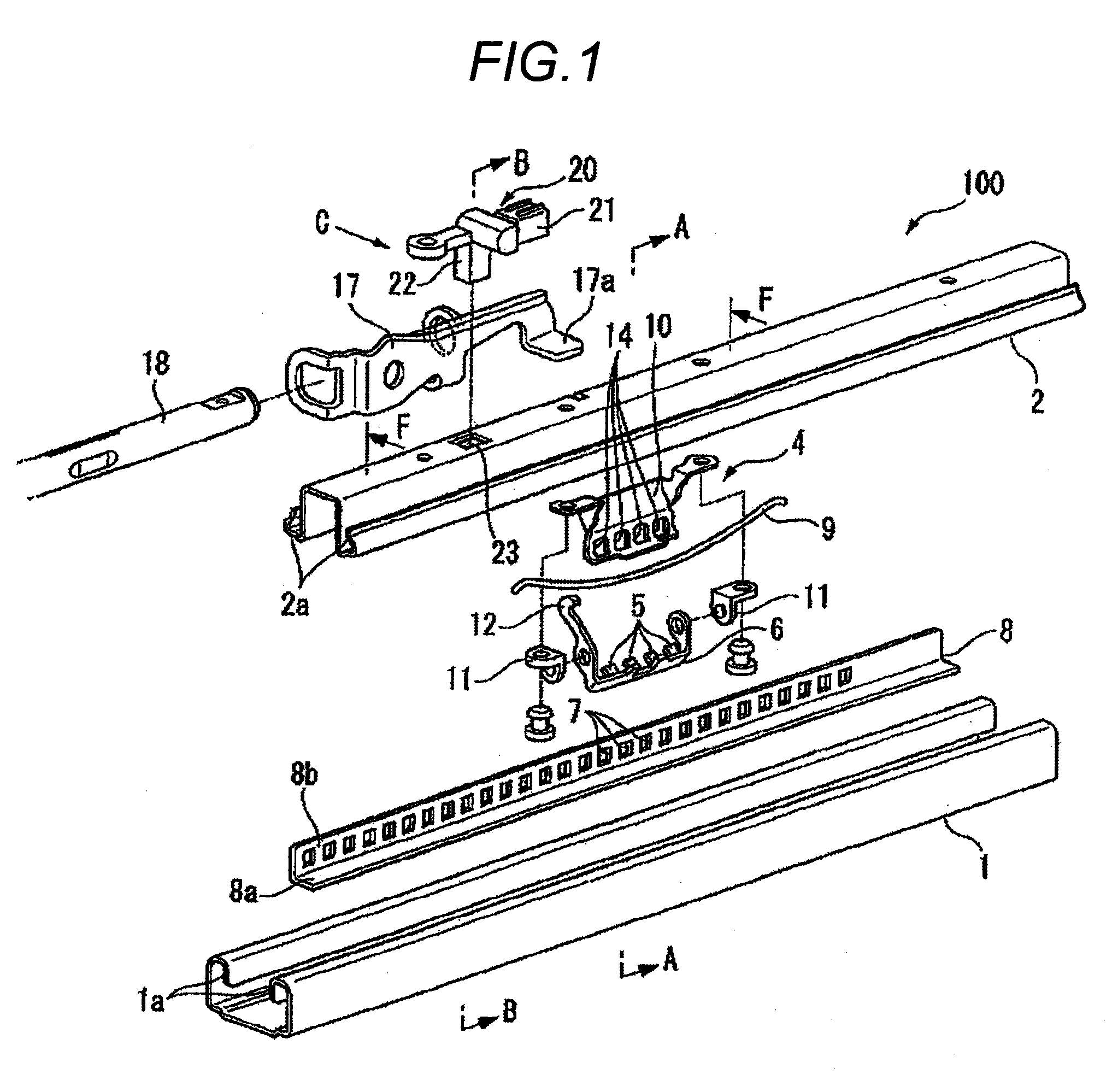
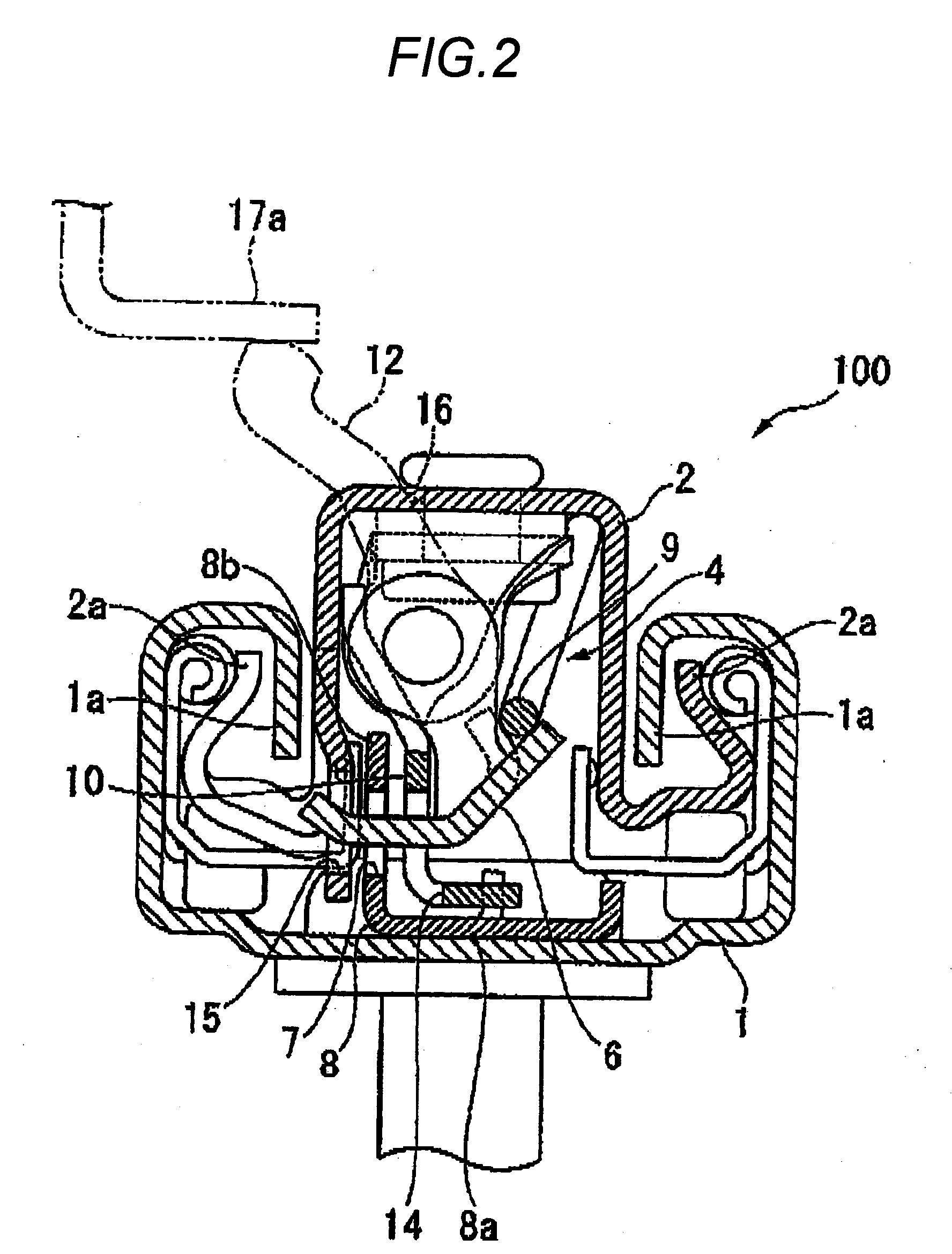
[0028]Next, description will be given below of an embodiment of a proximity sensor according to the invention with reference to FIGS. 1 through 8.

[0029]FIGS. 1 through 8 respectively show a seat slide apparatus for use in a vehicle. This seat slide apparatus incorporates therein a seat position detecting apparatus 100 which is used to detect the back and forth slide position of a seat for use in the vehicle. The detect signal of the seat position detecting apparatus 100 is used to control, for example, the developing output of an air bag or the ignition timing of an inflator according to the back and forth slide position of the seat.

[0030]As shown in FIG. 1, the seat slide apparatus includes a lower rail to be fixed to and installed on the floor of the vehicle and an upper rail 2 to be mounted on the lower surface of the seat, while the lower and upper rails 1 and 2 are assembled such that they may be slid in the longitudinal direction (in the back and forth direction of a vehicle b...


PUM


Abstract

In a proximity sensor 20 for detecting the proximity of a member to be detected 8 having a magnet or a magnetic material using a magnetic detection element 26, there are provided elastic members 33 for elastically energizing the magnetic detection element 26 toward the detection surface 26a thereof.

Description

[0001]The present invention claims priority from Japanese Patent Application No. 2007-215876 filed on Aug. 22, 2007, the entire content of which is incorporated herein by reference.BACKGROUND OF INVENTION[0002]1. Field of the Invention[0003]The present invention relates to a proximity sensor.[0004]2. Description of the Related Art[0005]As a position detecting apparatus for detecting the slide position of a seat for use in a vehicle, there is known an apparatus which uses a proximity sensor of a magnetic field detect type (see, JP-A-2006-281813 and JP-A-9-511357).[0006]According to this position detect apparatus a member to be detected made of a magnetic member is provided on a lower rail to be fixedly installed on the floor of a vehicle body. A proximity sensor including a magnetic field generating portion (a permanent magnet) and a detect portion (a Hall IC) is provided on an upper rail formed integrally with the vehicle seat.[0007]In this position detect apparatus, when the proxim...

Claims


Application Information

Patent Timeline
Patent Type & Authority Applications(United States)
IPC IPC(8): G01B7/14
CPCG01B7/023
Inventor NISHIDE, HARUTOMI
Owner HONDA MOTOR CO LTD
Learn More