Developer container, developing apparatus, process cartridge and image forming apparatus

Inactive Publication Date: 2015-05-07
CANON KK
View PDF7 Cites 9 Cited by
  • Summary
  • Abstract
  • Description
  • Claims
  • Application Information

AI Technical Summary

Benefits of technology

[0027]The present invention succeeds thus in providing a technology that all

Problems solved by technology

Accordingly, the sensitivity of the piezoelectric element, a

Method used


Image

  • Developer container, developing apparatus, process cartridge and image forming apparatus
  • Developer container, developing apparatus, process cartridge and image forming apparatus
  • Developer container, developing apparatus, process cartridge and image forming apparatus

Examples


embodiment 1

Schematic Configuration Diagram of an Image Forming Apparatus

[0042]FIG. 3 is a schematic cross-sectional diagram illustrating the schematic configuration of a process cartridge and an image forming apparatus according to an embodiment of the present invention. An example of a laser beam printer of detachable process cartridge type will be explained in the present embodiment as the image forming apparatus.

[0043]Herein, the term image forming apparatus (electrophotographic image forming apparatus) denotes an image forming apparatus in which an image is formed on a recording material (recording medium), by a developer (toner), as a result of an electrophotographic image forming process. Examples of the image forming apparatus include, for instance, electrophotographic copiers, electrophotographic printers (LED printers, laser beam printers and the like), electrophotographic fax machines and electrophotographic word processors, as well as multifunction machines (multifunction printers) ...

embodiment

Present Embodiment

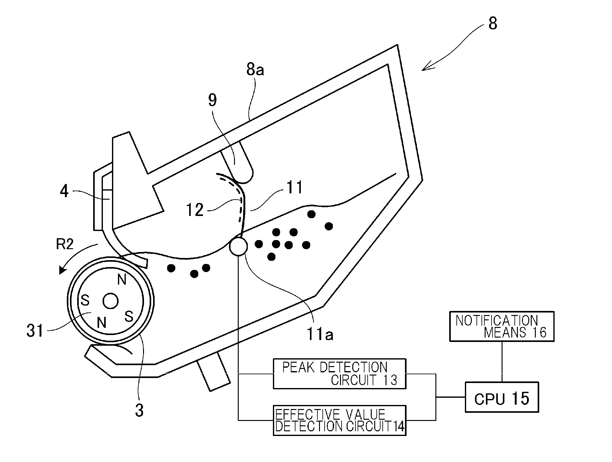
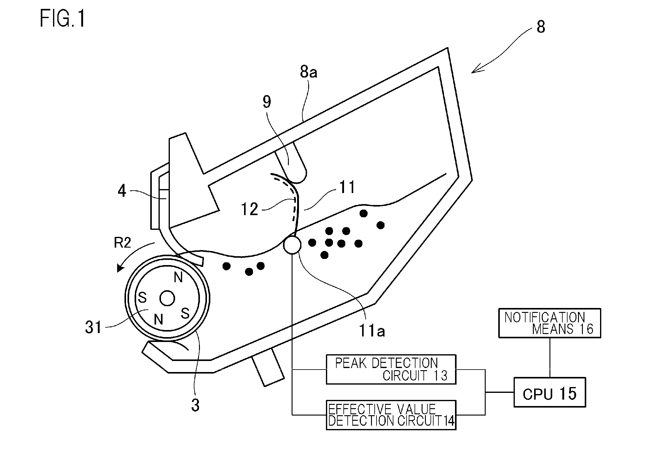
[0073]In the present embodiment a toner residual amount is detected by using a voltage peak value generated by the piezoelectric element 12 when the stirring member 11 contacts the reference-setting projection 9, and a voltage effective value that is generated by the piezoelectric element 12 while the stirring member 11 is immersed in the toner. In the present embodiment, a voltage detection means in the form of the peak detection circuit 13 and the effective value detection circuit 14 is connected to the piezoelectric element 12, such that a CPU 15, as a developer residual amount detection means, detects the toner residual amount on the basis of voltage values outputted by these circuits. The CPU 15 is also a control means for controlling the various operations of the image forming apparatus. The image forming apparatus is provided with a storage means in the form of a ROM, a RAM and the like, such that the CPU 15 performs various control processes by drawing on i...

embodiment 2

[0081]A developer container according to Embodiment 2 of the present invention will be explained next with reference to FIGS. 12A, 12B. Herein, FIGS. 12A, 12B are schematic cross-sectional diagrams illustrating the configuration of a developing apparatus according to the present embodiment, where FIG. 12A illustrates a schematic cross-sectional diagram of the developing apparatus of Embodiment 1, and FIG. 12B illustrates that of Embodiment 2. Only features different from those of Embodiment 1 will be explained herein. Features shared with Embodiment 1 will be denoted by the same reference symbols, and will not be explained again. Subject matter not explained herein is identical to that in Embodiment 1.

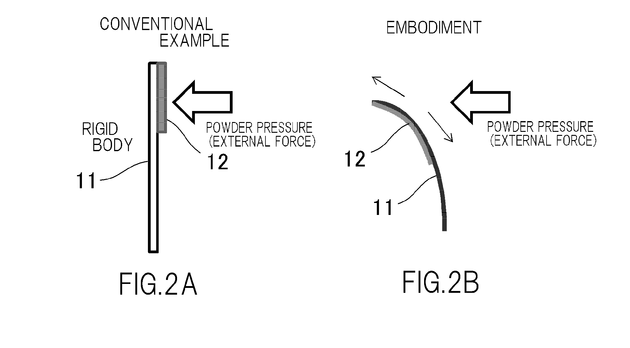
[0082]In a configuration where part of the wall of the developer container 8a, such as the reference-setting projection 9 of Embodiment 1, is caused to protrude, a toner jam may arise at the reference-setting position, as illustrated in FIG. 12A, due to scattering of toner when the sti...


PUM


Abstract

Provided is a technology that enhances the detection precision of the residual amount of a developer. An apparatus according to the invention includes: an accommodating portion in which a developer is accommodated; a sheet-like stirring member that, by rotating, stirs the developer accommodated in the accommodating portion; a piezoelectric element that is affixed to the stirring member and that outputs voltage when being deformed; and a deflection forming portion that comes in contact with the stirring member, thereby causing the stirring member to deflect, when a free end of the rotating stirring member is outside a developer accumulation region in the accommodating portion.

Description

BACKGROUND OF THE INVENTION[0001]1. Field of the Invention[0002]The present invention relates to a developer container, a developing apparatus, a process cartridge and an image forming apparatus.[0003]2. Description of the Related Art[0004]Developing assemblies that are used in image forming apparatuses such as electrophotographic printers or the like comprise ordinarily a developer container in which a developer (toner) is accommodated, and a developing roller, rotatably provided at an opening of the developer container, and which carries and transports the developer from inside the developer container. The developer inside the developer container is stirred through rotation of a stirring member that is provided inside the developer container, is transported by the developing roller, and is consumed thereupon by being used to develop an electrostatic latent image.[0005]Herein, Japanese Patent Application Publication No. H3-271785 discloses, as a method for detecting a residual amou...

Claims


Application Information

Patent Timeline
IPC IPC(8): G03G15/08
CPCG03G15/0889G03G15/0858
Inventor MATSUKAWA, AKIHISAKAINO, TOSHIYAMOCHIZUKI, KEISUKENOGUCHI, BUNROSATO, SHUNSHIBATA, MASAHIROMITSUI, YOSHIHIROYAMAUCHI, HISASHI
Owner CANON KK
Why Eureka
Try Eureka