Battery state of charge detection

a battery and state detection technology, applied in the direction of propulsion parts, process and machine control, electric devices, etc., can solve the problems of decreasing computation precision of soc, inability to measure current in the instantaneous rated discharge range, and reducing the resolution of the sensor, so as to increase the detection precision of soc

Inactive Publication Date: 2009-09-08
NISSAN MOTOR CO LTD
View PDF20 Cites 10 Cited by
  • Summary
  • Abstract
  • Description
  • Claims
  • Application Information

AI Technical Summary

Benefits of technology

[0006]It is therefore an object of this invention to increase the detection precision for the SOC across a wide range.

Problems solved by technology

Expanding the range over which the current sensor takes measurements causes a decrease in the resolution of the sensor, and this causes the computation precision for the SOC to decrease.
However, the current in the instantaneous rated discharge range cannot be measured.

Method used


Image

  • Battery state of charge detection
  • Battery state of charge detection
  • Battery state of charge detection

Examples


Embodiment Construction

[0015]This invention is capable of being applied to a motor driver circuit of an electric vehicle, a hybrid-drive vehicle, or the like. Embodiments of this invention as applied to a motor driver circuit like those described above are explained below.

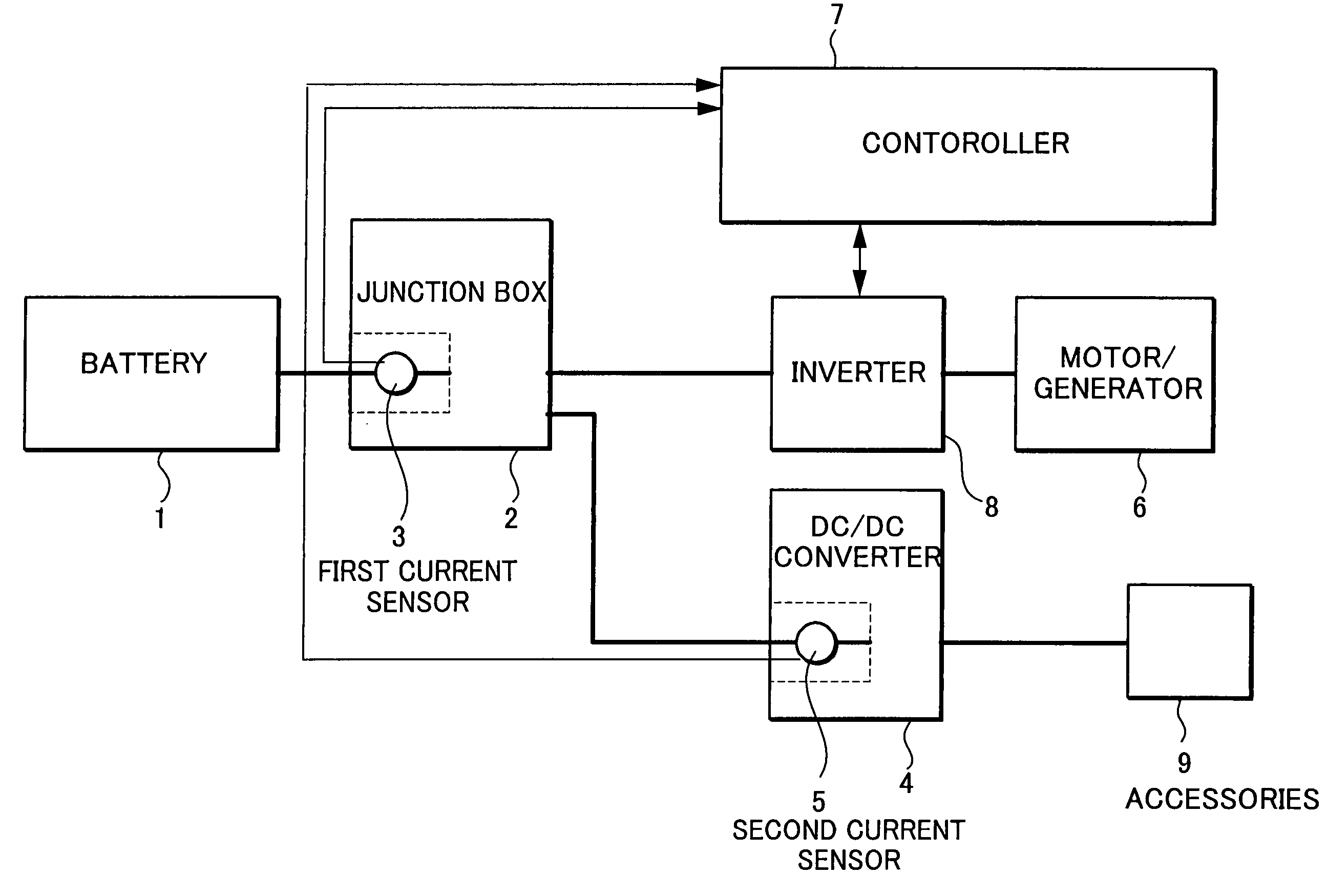
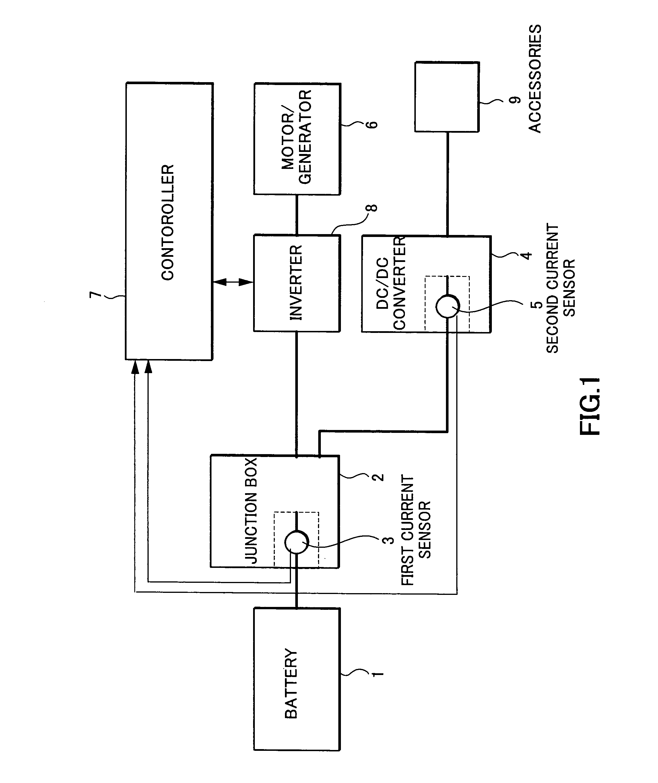
[0016]Referring to FIG. 1 of the drawings, a driver circuit of a motor / generator 6 used in driving a vehicle comprises a battery 1, a junction box 2, a DC / DC converter 4, and a controller 7.

[0017]The battery 1 supplies a direct current to an inverter 8 through the junction box 2. The inverter 8 converts the direct current supplied from the battery 1 into an alternating current, and supplies the alternating current to the motor / generator 6.

[0018]The battery 1 supplies a direct current to the DC / DC converter4 through the junction box 2. The DC / DC converter 4 converts a voltage of the direct current supplied from the battery 1 into a lower voltage, and supplies the direct current to the accessories 9.

[0019]The motor / generator 6 rotates due ...


PUM


Abstract

A state of charge of a battery (1) that drives a motor (6) is computed based on a discharge current measured by a current sensor (3) when the discharge current of the battery (1) does not exceed a rated discharge range of the battery (1). When the discharge current of the battery (1) exceeds the rated discharge range, the state of charge of the battery (1) is computed by estimating the discharge current of the battery (1) from a motor control signal, whereby current changes over a wide range can be found with good precision using the sensor (3), which has a narrow but high resolution measurable range, and the state of charge can be accurately detected.

Description

FIELD OF THE INVENTION[0001]This invention relates to detection of the state of charge of a battery for an electric vehicle or a hybrid-drive vehicle.BACKGROUND OF THE INVENTION[0002]JP 9-84205 A, published by the Japan Patent Office in 1997, discloses a device that computes a state of charge (hereinafter abbreviated to “SOC”) for a battery by measuring a battery discharge current and adding up current values.[0003]The battery SOC is computed by using electric current sensors capable of covering both a rated discharge range at which the battery is capable of producing continuous discharge, and a high power instantaneous rated discharge range where the battery is capable of performing discharge for a short period of time.SUMMARY OF THE INVENTION[0004]Expanding the range over which the current sensor takes measurements causes a decrease in the resolution of the sensor, and this causes the computation precision for the SOC to decrease.[0005]On the other hand, a current sensor that cove...

Claims


Application Information

Patent Timeline
Patent Type & Authority Patents(United States)
IPC IPC(8): H02J7/00G01R31/36B60L3/00B60W10/26B60W20/00
CPCG01R31/3606G01R31/382
Inventor HIRATA, TAKESHIYAMANAKA, TSUYOSHINAKADA, YUJI
Owner NISSAN MOTOR CO LTD
Why Eureka
Try Eureka